„Experiments with microwaves” változatai közötti eltérés
| (egy szerkesztő 38 közbeeső változata nincs mutatva) | |||
| 78. sor: | 78. sor: | ||
===Bending of waves (diffraction)=== | ===Bending of waves (diffraction)=== | ||
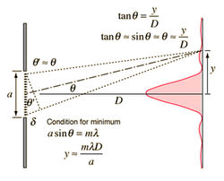
| − | <span id="fig:2">[[Fájl:Mikrohulla diffrakcio.jpg|bélyegkép|250px|jobb|Fig. 2]]</span> | + | <span id="fig:2">[[Fájl:Mikrohulla diffrakcio.jpg|bélyegkép|250px|jobb|Fig. 2: Diffraction on single slit]]</span> |
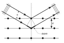
| − | <span id="fig:3">[[Fájl:Mikrohulla bragg racs.jpg|bélyegkép|250px|jobb|Fig. 3]]</span> | + | <span id="fig:3">[[Fájl:Mikrohulla bragg racs.jpg|bélyegkép|250px|jobb|Fig. 3: Bragg diffraction]]</span> |
Peculiar phenomena can be observed if the wave travels in a medium containing inhomogeneities of size comparable to the wavelength. For example when the wave meets small-sized inpenetrable obstacle(s) or penetrable slit(s) located on an inpenetrable medium boundary. After passing through the obstacle or slit characteristic direction dependence appears in the intensity of the plane wave having originally uniform spatial intensity distribution. This is called ''diffraction'' or bending of waves (since in this case the wave differs from its original direction, it penetrates into the space behind the obstacle). | Peculiar phenomena can be observed if the wave travels in a medium containing inhomogeneities of size comparable to the wavelength. For example when the wave meets small-sized inpenetrable obstacle(s) or penetrable slit(s) located on an inpenetrable medium boundary. After passing through the obstacle or slit characteristic direction dependence appears in the intensity of the plane wave having originally uniform spatial intensity distribution. This is called ''diffraction'' or bending of waves (since in this case the wave differs from its original direction, it penetrates into the space behind the obstacle). | ||
| 104. sor: | 104. sor: | ||
===Components of the equipment=== | ===Components of the equipment=== | ||
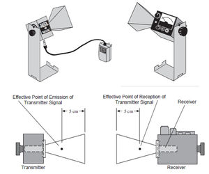
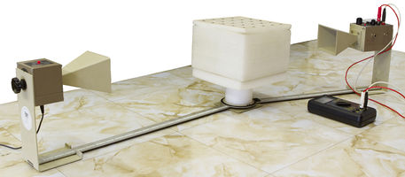
| − | <span id="fig:4">[[Fájl:Mikrohulla gunn.jpg|bélyegkép|300px|jobb|Fig. 4]]</span> | + | <span id="fig:4">[[Fájl:Mikrohulla gunn.jpg|bélyegkép|300px|jobb|Fig. 4: Microwave transmitter (left) and receiver (right)]]</span> |
| + | In the exercise microwaves are generated with special transmitter by using Gunn diode, and are radiated through a rectangular shaped funnel ([[#fig:4|Fig. 4]]). The waves are polarized in the direction parallel to the longitudinal axis of the diode. The plane of polarization of the waves can be changed in the experiment by loosening the screw located on the back of the transmitter. Then the transmitter can be rotated about the horizontal axis, and the angle of rotation can be read from the scale. The transmitter is turned on if the LED indicates. | ||
| + | The funnel of the receiver for detecting microwaves collects the incident waves onto Schottky diode which detects the intensity of the wave ([[#fig:4|Fig. 4]]) and it works as a polarizer in the direction parallel to its longitudinal axis. In case of not too large intensities the deflection of the indicator of the instrument located on the receiver is approximately proportional to the intensity of the wave. Like the transmitter, the receiver can be rotated about the horizontal axis. It can be switched on if "Intensity" button is turned from "OFF" to "30x", and its operation is indicated by the LED. The amplification can be increased by turning Intensity button to a range position with lower multiplication factor. The measured quantity is the value read by the instrument multiplied by the factor of the range position. | ||
| + | At the beginning of every measurement it is advisable to adjust the sensitivity of the receiver: The receiver is placed in the direction of the signal to be measured using the same funnel position as the transmitter, and "Variable Sensitivity" button is to turn until the indicator is in the middle of the scale. If it is impossible to do using the lowest amplification ("30x" position), the amplification is to increase by "Intensity" button (this means decreasing multiplication factor) until the indicator is in the middle of the scale. During the exercise do not change this adjusment. | ||
| + | There are other tools which are useful. These are shown in [[#fig:9|Fig. 5]]. On the red and black banana jacks with label "Output" voltage between 0-2 V appears proportionally to the current read by the instrument with indicator. | ||
| + | |||
| + | {| | ||
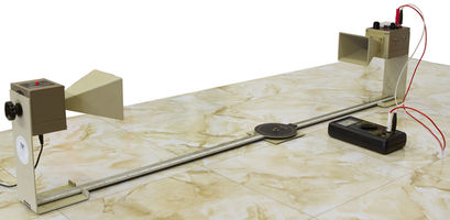
| + | |<span id="fig:5">[[Fájl:Mikrohulla 5544i.jpg|bélyegkép|x200px|bal|The microwave transmitter (left) and the receiver (right) on a goniometer]]</span> | ||
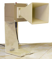
| + | |<span id="fig:6">[[Fájl:Mikrohulla 5562i.jpg|bélyegkép|x200px|közép|The microwave transmitter on a stand]]</span> | ||
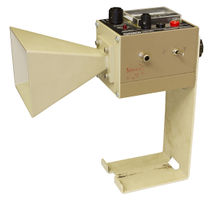
| + | |<span id="fig:7">[[Fájl:Mikrohulla 5563i.jpg|bélyegkép|x200px|közép|The microwave receiver on a stand]]</span> | ||
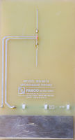
| + | |<span id="fig:8">[[Fájl:Mikrohulla 5564i.jpg|bélyegkép|x200px|jobb|Antenna for receiving standing waves ]]</span> | ||
| + | |} | ||
| + | |||
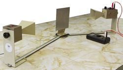
| + | <span d="fig:9">[[Fájl:Mikrohulla eszkozok.jpg|bélyegkép|550px|közép|Fig. 5: Accessories of the experimental setup: Goniometer (one of its arms can be rotated, arms with scale, axis with angle scale); fixed arm assembly; rotating table; slidable component holder with magnetic fastening surface; rotating component holder with magnetic fastening surface; metal reflector; partial reflector; cubic lattice with metal spheres (for Bragg reflection); polyethylene panel; prism container made of ethafoam; styrene balls to fill the prism container, tubular plastic bag; how to place the component holder onto the goniometer]]</span> | ||
| + | |||
| + | In the followings the experimental setups are demonstrated giving sketch. In the figures numbering of [[#fig:9|Fig. 5]] is used. | ||
| + | |||
| + | ===Examination of refelection=== | ||
| + | |||
| + | <span id="fig:10">[[Fájl:Mikrohulla 5559i.jpg|bélyegkép|250px|jobb|Fig. 6: Measuring of law of reflection]]</span> | ||
| + | |||
| + | Reflection of waves is measured with goniometer using the setup shown in [[#fig:10|Fig. 6]]. Place the receiver on the rotating arm of the goniometer, and the metal reflector on the rotating component holder. Angle of incidence can be changed by rotating the metal reflector, reflected wave can be found by rotating the arm of the goniometer holding the receiver. Angles can be measured by using the angle scale on the goniometer. | ||
| + | |||
| + | ===Examination of standing waves=== | ||
| + | |||
| + | <span id="fig:11">[[Fájl:Mikrohulla 5550i.jpg|bélyegkép|250px|bal|Fig. 7 Examination of standing waves. Probe is located in the middle, on the right the metal reflector can be seen]]</span> | ||
| + | |||
| + | The sketch can be seen in [[#fig:11|Fig. 7]]. This exercise differs from the others as the intensity of the wave is measured by a special probe not by the receiver directly. The probe can be connected to the receiver, and its signal can be read by the instrument with indicator located on the receiver. | ||
| + | Standing waves are generated between the transmitter and the metal reflector if their distance fulfills the condition for observing standing waves. The appropriate distance can be adjusted by moving the metal reflector. By moving the probe the position dependence of the amplitude can be measured. Knowing this and using eq. [[#eq:10|(10)]] the wavelength can be determined. To have better accuracy, measure the distance between the first and eleventh found maxima, not between to adjacent ones. | ||
| + | |||
| + | ===Refraction on a prism=== | ||
| + | |||
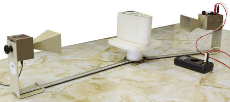
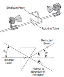
| + | The setup is to see in [[#fig:12|Fig. 8]]. First study the affect of the empty prism container for the propagation of microwaves. Then fill up the prism container with styrene balls. In order to evaluate easily, rotate the prism by using the rotating table into the position in which one of the sides of the prism is perpendicular to the direction of the incident wave ([[#fig:13|Fig. 9]]). Find the refracted wave by rotating the arm of the goniometer holding the transmitter. The refractive index of the material filled the prism relative to the air and the speed of wave in the prism can be determined from eq. ([[#eq:2|2]]). | ||
| + | |||
| + | {| | ||
| + | |<span id="fig:12">[[Fájl:Mikrohulla 5548i.jpg|bélyegkép|x200px|közép|Fig. 8: Measuring the refraction index of prism located in the middle ]]</span> | ||
| + | |<span id="fig:13">[[Fájl:Mikrohulla tores prizman.jpg|bélyegkép|x250px|közép|Fig. 9: Experimental setup and perpendicular incidence]]</span> | ||
| + | |} | ||
| + | |||
| + | ===Examination of polarization=== | ||
| + | |||
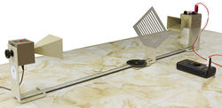
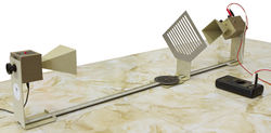
| + | In this exercise use opposed transmitter and receiver, and for some tests place the metal grid as polarizer between them ([[#fig:14|Fig. 10a]] and [[#fig:15|Fig. 10b]]). The affect of the position of the polarizer for a polarized wave can be studied without using extra polarizer by rotating the receiver about the horizontal axis since the receiver is a polarizer, as well. With the setup the affect of the polarizer with different directions placed between the transmitter and the receiver can also be examined. | ||
| + | |||
| + | {| | ||
| + | |<span id="fig:14">[[Fájl:Mikrohulla 5551i.jpg|bélyegkép|250px|bal|Fig. 10a: Examination of polarization of waves using metal grid]]</span> | ||
| + | |<span id="fig:15">[[Fájl:Mikrohulla 5554i.jpg|bélyegkép|250px|közép|Fig. 10b: Examination of polarization of waves using metal grid with rotated receiver]]</span> | ||
| + | |} | ||
| + | |||
| + | ===Diffraction of slit=== | ||
| + | |||
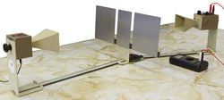
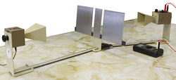
| + | Diffraction can be examined by using single slit and double slit according to setups in [[#fig:16|Fig. 11a]] and [[#fig:17|Fig. 11b]]. In case of double slit set 1.5 cm slit size, in case of single slit remove the middle slit spacer and use ~7 cm slit size. | ||
| + | |||
| + | {| | ||
| + | |<span id="fig:16">[[Fájl:Mikrohulla 5556i.jpg|bélyegkép|250px|bal|Fig. 11a: Diffraction on double slit using wide slit spacer]]</span> | ||
| + | |<span id="fig:17">[[Fájl:Mikrohulla 5557i.jpg|bélyegkép|250px|közép|Fig. 11b: Diffraction on double slit using narrow slit spacer]]</span> | ||
| + | |} | ||
| + | |||
| + | |||
| + | ===Lloyd's mirror=== | ||
| + | |||
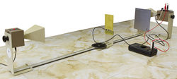
| + | By means of Lloyd's mirror wavelength can be measured by examining the interference of waves coming from the same source but traveling different paths (paths AC and ABC in [[#fig:18|Fig. 12]]). In the experiment at first approach mirror B to the axis of the goniometer. The receiver detects consecutive maxima and minima depending on that the path difference in C fits to eq. [[#eq:6|(6)]] or eq. [[#eq:7|(7)]]. Stop closest to the goniometer where maximum signal is observed, and measure distance $h_1$ where the mirror is located. Then move away the mirror from line AC until maximal intensity is observed again, and measure distance $h_2$ of the mirror. Also if we measure the distance between the transmitter and the receiver the original path (belongs to $h_1$) and the new path (belongs to $h_1$) can be determined. In this case the path difference between the waves is $\lambda$ according to eq. [[#eq:6|(6)]]. Make sure that the axis of the transmitter and that of the receiver are located on the same straight line, and both the transmitter and the receiver are placed at the same distance from the axis of the goniometer, and the distance between them is at least 1 m. The plane of the mirror has to be parallel to the straight line between the transmitter and the receiver. Take into account the locations of effective points given in [[#fig:4|Fig. 4]] when distances are being determined. | ||
| + | |||
| + | {| | ||
| + | |<span id="fig:18">[[Fájl:Mikrohulla llyod tukor.jpg|bélyegkép|x300px|bal|Fig. 12: Different paths of two waves]]</span> | ||
| + | |<span id="fig:19">[[Fájl:Mikrohulla 5558i.jpg|bélyegkép|300px|közép|Measuring wavelength by using Lloyd's mirror (in the middle)]]</span> | ||
| + | |} | ||
| + | |||
| + | ===Michelson interferometer=== | ||
| + | |||
| + | <span id="fig:20">[[Fájl:Mikrohulla 5566i.jpg|bélyegkép|300px|jobb|Fig. 13: Michelson interferometer. Transmitter is on the front right, mirror A is in the rear middle, mirror B is on the rear right, partial reflecting mirror (C) is in the middle, receiver on the left]]</span> | ||
| + | |||
| + | The sketch of the interferometer, which is useful for measuring wavelength and displacement, can be seen in [[#fig:20|Fig. 13]]. Similarly to Lloyd's mirror, wave coming from a source is divided into two parts, and they are guided in different paths then meet. At the meeting point the waves interfere, and the result (constructive or destructive interference) depends on the difference of the guided paths. In the figure a part of the wave coming from the transmitter is reflected by mirror C to mirror B, the other part goes through mirror C to mirror A. Then a part of the wave reflected by mirror B traveling through mirror C and a part of the wave reflected by mirror A being reflected by mirror C go into the receiver which detects signal according to the interference of two waves. The path difference is the difference of distances 2$\cdot$BC and 2$\cdot$AC. | ||
| + | At first find a position of mirror A when the receiver reads maximum intensity (for the path difference condition [[#eq:6|(6)]] is fulfilled), then move away the mirror from mirror C until maximum signal is observed again. The distance between the two positions of mirror A is equal to $\lambda/2$ since the path difference is $\lambda$. To measure more accurate move the mirror to a distance corresponding to 10 new maxima. | ||
| + | |||
| + | ===Measuring of Brewster's angle=== | ||
| + | |||
| + | <span id="fig:21">[[Fájl:Mikrohulla 5549i.jpg|bélyegkép|250px|jobb|Fig. 14: Measuring of Brewster's angle on polyethylene panel]]</span> | ||
| + | |||
| + | Accomplish the measurement according to the sketch seen in [[#fig:21|Fig. 14]]. Set horizontal polarization for the transmitter and for the receiver (90° on the scale of their backs), rotate the polyethylene panel until the angle of incidence of the wave coming from the transmitter is about 20°. By rotating the arm of the goniometer holding the receiver find the wave reflected by the panel (maximum intensity), and record the measured intensity. In this position repeat the measurement with transmitter and receiver of vertical polarization (rotate them into 0°). Repeat this exercise with more different angle of incident. In case of Brewster's angle the horizontally polarized wave is not reflected since the vertical panel acts as a vertical polarizator for the reflected wave. | ||
| + | |||
| + | ===Bragg diffraction by cubic lattice=== | ||
| + | |||
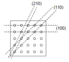
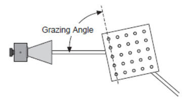
| + | The experimental setup is shown in [[#fig:22|Fig. 15a]]. The task is to find the angles $\Theta_n$ according to [[#eq:13|(13)]] Bragg's equation in case of different vertical diffraction planes ([[#fig:23|Fig. 15b]]) (Three numbers indicating the diffraction planes are Miller indices of the planes. These numbers are proportional with the reciprocal of intercepts of the plane and the coordinate system parallel to the edges of the cube). Remember that the angle in eq. [[#eq:13|(13)]] is not the angle of incidence but it is the angle between the wave and the diffraction plane ([[#fig:24|Fig. 15c]]). | ||
| + | In case of plane (100) the following is the measuring process: Place the transmitter opposite to the receiver, and put the lattice on the rotating table in a way that the (100) planes are parallel to the direction of the incident wave, and record the intensity. Rotate the lattice by means of the rotating table by 1°, and rotate the arm of the goniometer holding the receiver by 2° clockwise. Record angle $\Theta$ and the intensity. Keep rotating and measuring, and plot the intensity as a function of the angle of incidence. Maximum has to be found at angles according to Bragg's equation. By using eq. [[#eq:13|(13)]] distances between planes (100) can be determined. For another planes similar steps has to be taken. | ||
| + | |||
| + | {| | ||
| + | |<span id="fig:22">[[Fájl:Mikrohulla 5547i.jpg|bélyegkép|x200px|bal|Fig. 15a: Bragg diffraction on a cubic lattice located in the middle]]</span> | ||
| + | |<span id="fig:23">[[Fájl:Mikrohulla kristalysikok.jpg|bélyegkép|x200px|közép|Fig. 15b: Different diffraction planes]]</span> | ||
| + | |<span id="fig:24">[[Fájl:Mikrohulla bragg elrendezes 2.jpg|bélyegkép|x200px|jobb|Fig. 15c: The angle in Bragg's equation]]</span> | ||
| + | |} | ||
| + | |||
| + | ==Measuring tasks== | ||
| + | |||
| + | # By using prism container determine the refraction index of styrene balls relative to air and the speed of wave in this medium. | ||
| + | # Place the transmitter opposite to the receiver in the same direction of polarization (0° on the backs of the instruments, longitudinal axes of funnels are horizontal.) Then rotate the receiver about its horizontal axis and measure how the intensity depends on the angle of the direction of the receiver (from 0° to 180°, using 10° steps). Interpret the results. In case of vertical polarization of the transmitter and the receiver (0°) place the metal grid polarizer with horizontal slit position between the transmitter and the receiver, and by rotating the receiver measure the angle dependence of the intensity. Repeat the measurement when the angle between the slits of the polarizer and the horizontal is 22,5°, 45°, 67,5° and 90°. Interpret the results. Place the transmitter and the receiver in a way that their direction of polarization is perpendicular to each other. Measure the intensity without the metal grid polarizer, then place the metal grid polarizer, and measure the intensity when the slits of the polarizer is horizontal, vertical, and at 45° with the horizontal. Interpret the results. | ||
| + | # Assemble the setup for measuring double slit diffraction using narrow slit spacer, and 1,5 cm slit size. Place the transmitter opposite to the receiver using vertical polarization (0°). Then by rotating the arm of the goniometer holding the receiver measure and plot how the intensity depends on the angle (between 0° and 85° using 5° steps). Verify eqs. [[#eq:11|(11)]], [[#eq:12|(12)]] (calculate the wavelength from the frequency given on the transmitter) and interpret the differences. Repeat the measurement using wide slit spacer (place the receiver at 1.5 times larger distance from the slit). Accomplish the measurement using single slit of 7 cm slit size and verify eq. [[#eq:11|(11)]]. | ||
| + | # Measure the wavelength of the applied microwave with Lloyd's mirror using two different transmitter-receiver distances. Compare this result with the previous one. | ||
| + | # Measure the wavelength of the applied microwave with Michelson interferometer using two different initial positions of mirror A. Compare the results with each other and with previous ones. | ||
| + | # By using the setup for measuring Brewster's angle measure and plot the angle dependence of the intensity of the microwave reflected by the polyethylene panel. Change the angle of incidence between 20° and 75° per 5°. At first the polarization of the transmitter and the receiver is horizontal, then the polarization is vertical. Interpret the results and determine Brewster's angle. | ||
| + | # By using Bragg diffraction determine the distances between planes (100), (110) and (210), respectively in the given cubic lattice. Compare the results with the direct measurement of the distances. | ||
| + | |||
| + | Optional tasks (if you have time): | ||
| + | |||
| + | |||
| + | # Verify eq. [[#eq:1|(1)]] for reflecting microwaves. Change the angle of incidence between 10° and 90° per 10°. Make a table and interpret the possible deviations from the law of reflection. | ||
| + | # Generate standing waves, and measure the wavelength of the applied microwave. Calculate the frequency of the wave (wave of propagation is given). Accomplish the measurement using two different settings. | ||
| + | |||
| + | ==Important safety informations== | ||
| + | |||
| + | '''Since the reflection of microwaves by any other objects near effects the measurement, remove every unused obejct from the table (especially metallic objects).''' | ||
| + | '''Microwaves are reflected by the human body, as well. Never be in a position which reflects the waves coming from the transmitter to the receiver. The best option is when the measurement is done standing behind the plane of the funnel of the receiver.''' | ||
| + | '''Although, the power of the transmitter is well below the permitted safety value, never look into the funnel of the transmitter directly when it is turned on.''' | ||
| + | '''It may happen (but not likely) that the microwaves disturb the operation of some medical devices (for example pacemaker). If you use this kind of devices, please tell it to the instructor.''' | ||
</wlatex> | </wlatex> | ||
A lap jelenlegi, 2018. július 10., 19:53-kori változata
Aim of the experiment
- To deepen the knowledge related to wave phenomena,
- To verify the relationships in wave physics experimentally,
- To model phenomena and devices in wave optics.
For the purpose:
- We summarize the basic knowledge on wave phenomena,
- We examine reflection, refraction, interference and diffraction of microwaves,
- We assemble some experimental setups (which are also useful in optics) based on interference of waves, and measure the wavelength of the used microwave.
Theoretical summary
In the experiment we use microwaves to study wave phenomena. Microwaves - as well as light - are electromagnetic waves of wavelength about 1 mm - 30 cm (correspondingly, the frequency of microwaves is  ).
).
Polarization of waves
In a transversal wave the vector related to the changing quantity is in the plane perpendicular to the direction of propagation but within this plane its direction is arbitrary. A certain direction of oscillation can be selected by putting a block in the path of the wave. This way behind the block a wave can be observed in which the oscillation takes place in the plane determined by the selected direction of the block and the direction of propagation. This type of wave is plane polarized wave, and the method is called polarization of waves. The selected plane is the plane of polarization, the block which creates the polarized wave is called polarizer, and usually for the selected direction direction of polarization is said. Different kind of waves can be polarized by using different methods: Transversal waves on a string or rope with a slit, electromagnetic waves with a mirror or with an equipment made of special material, microwaves with metal grating. Polarized waves have a characteristic property, namely they can be canceled out by using a polarizer of direction perpendicular to the plane of the oscillation. In case of electromagnetic waves the above definition of polarization is not unambiguous since in the plane perpendicular to the direction of propagation there are two vectors perpendicular to each other. By agreement in this case the plane of polarization is the plane containing the electric field vector.
Reflection and refraction of waves
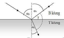
Waves propagate in finite sized medium, sooner or later they reach the boundary of the medium (for electromagnetic waves the madium can be vacuum). According to experience waves are partially reflected by the boundary, and partially refracted by the boundary, penetrating in the other medium generally by changing its direction of propagation. By using the notations of Fig. 1 laws of reflection and refraction are as follows.
In case of refection the angle of incidence ( ), which is the angle between the direction of incident plane wave and the normal of the reflected surface, is equal to the angle of reflection (
 ), which is the angle between the direction of reflected wave and the surface normal:
![\[ \alpha_\text b = \alpha_\text v. \]](/images/math/9/8/9/989b253ff375166dfe1cd758784bd9aa.png)
In case of refraction Snell's law is valid:
![\[ \frac{\sin \alpha_\text b}{\sin \alpha_\text t}= \frac{c_\text b}{c_\text t}=n_\text{tb},\]](/images/math/3/4/b/34bf15ac3f77c4770dc2f1e425c2881e.png)
where  is the angle of refraction, which is the included angle of the direction of refracted wave and the surface normal. In the medium in which the incident wave propagates (medium B in Fig. 1) the speed of propagation is
  , and that in the medium of the refracted wave is
  (medium T in Fig. 1). The ratio of these speeds (
 ) is the relative refractive index, the refractive index of medium T if the wave comes from medium B. If medium B is vacuum, the absolute refractive index is used. If the absolute refractive indices are
  and
and  for media B and T, respectively, it can be shown that:
![\[ n_\text{tb} = \frac{n_\text t}{n_\text b}.\]](/images/math/7/1/d/71dbd6901c7aba75a835d87155305515.png)
When  is smaller than 1 (
 ), increasing the angle of incidence the angle of refraction becomes
  . Further increasing the angle of incidence the boundary behaves like a mirror, the wave is reflected according to the law of reflection. This is called total internal reflection, and the angle of incidence
  belonging to the angle of refraction
  is the critical angle:
![\[ \sin \alpha_\text{bh} = n_\text{tb}.\]](/images/math/d/6/d/d6ddc391d19ab5a36f932ef97a197403.png)
On reflection and refraction the phase of the wave may change, in case of electromagnetic wave even its polarization. It is an important experience in practice that for a certain angle of incidence the reflected electromagnetic wave becomes plane polarized. The plane of polarization of the reflected wave is perpendicular to the plane of incidence, which is determined by the direction of the incident and the reflected waves and the surface normal (electric field vector of the reflected wave is parallel to the reflected surface). It can be shown that this happens if the directions of the refracted and the incident waves are perpendicular to each other (in Fig. 1  ), from which it follows that
![\[\tan \alpha_\text{b,B}= n_\text{tb}.\]](/images/math/e/6/2/e62f03e98ce0b67c198258e5cf4efc06.png)
This is called Brewster's law, and  is Brewster's angle.
Interference of waves
In the examined part of space simultaneously more waves can propagate. In this case the resultant oscillation pattern can be determined mostly by means of superposition principle: the instantaneous values of the wave functions should be added. This is called interference, which depends on the phases of the meeting waves. In the extreme case the amplitudes can add if the phases of the waves are the same (constructive interference), or they can subtract, moreover in case of equal amplitudes they can cancel out each other, if the phases of the waves are opposite (destructive interference). If the phase of the wave sources does not change in time, and uninterrupted, regular traveling waves of equal frequencies are examined (called coherent waves), the phase difference at the location of summation is determined by the phase difference of the wave sources and the path difference between the waves until reaching that location. This means that for coherent waves the amplitude of the wave at any any locations is constant in time, which results in a steady spatial amplitude distribution (for visible waves the interference pattern can be observed by eye). For instance in case of two in-phase sources the phase difference in the interference of two harmonic waves is specified by the path difference only. If the wave sources are at distances  and
and  from the location of the examined point, constructive interference is observed in those points for which the path difference is an integer number multiple of the wavelength:
![\[ \Delta s_n = n \lambda, \quad \left( n=1,2,3,...\right),\]](/images/math/7/7/d/77d40d814ef28341ad0e2ee37eb888ae.png)
destructive interference is observed in those points for which the path difference is an odd number multiple of the half wavelength:
![\[ \Delta s_n = \left( 2n-1 \right) \frac{\lambda }{2}, \quad \left( n=1,2,3,...\right).\]](/images/math/1/b/9/1b9d31aeab45124c1588d3184cf7d062.png)
Standing waves
Formation of standing waves is an important special case of interference of waves: it is due to the fact that the wave is at least partially reflected at the boundary of a medium. Under certain circumstances interference of waves traveling to the boundary and being reflected from it results in a specific steady waveform, standing wave. Characteristics of standing waves is that at certain points of the medium oscillation takes place in the same phase, the amplitude depends on the location only.
Standing wave can be formed for example in a medium between two planes perpendicular to the direction of the reflected harmonic plane wave only if its wavelength (frequency) fulfills certain conditions. The possible wavelengths of the standing wave is determined by the distance  between the two reflecting planes and by the boundary conditions at the locations of reflection. The physical conditions at the boundary are such that oscillation cannot be formed there (for example elastic string with fixed ends, an oscillating air column between solid walls, or a metal surface reflecting the electric component of the electromagnetic wave). In other cases there is no restriction (or hardly any) for the formation of oscillation at the boundary (for example at the free ends of an elastic string, at the open end of a gas column, on the magnetic component of the electromagnetic wave at a reflecting metal surface).
It can be shown if the oscillation is restricted or unrestricted on both ends of a medium of length
  , the possible wavelengths is given by
![\[ \lambda_n = \frac{2L}{n}, \quad \left( n=1,2,3,...\right).\]](/images/math/3/b/2/3b20f5dceca66209fec5fbf867048bf4.png)
If it is restricted on one of the ends and the other is free
![\[ \lambda_n = \frac{4L}{2n-1}, \quad \left( n=1,2,3,...\right).\]](/images/math/6/c/1/6c164583679754d2ffc2c621af210ac9.png)
In such a standing wave along the direction of wave propagation the amplitude depends on the location as sine (cosine) function, and accordingly, the amplitude distribution contains maxima (antinodes) and minima (nodes). The distance between two nodes or two antinodes is given by
![\[ d_n = \frac{\lambda_n}{2}, \quad \left( n=1,2,3,...\right).\]](/images/math/a/c/6/ac6cb5e7fc7cbd1a42ddc85d53f58902.png)
Bending of waves (diffraction)
Peculiar phenomena can be observed if the wave travels in a medium containing inhomogeneities of size comparable to the wavelength. For example when the wave meets small-sized inpenetrable obstacle(s) or penetrable slit(s) located on an inpenetrable medium boundary. After passing through the obstacle or slit characteristic direction dependence appears in the intensity of the plane wave having originally uniform spatial intensity distribution. This is called diffraction or bending of waves (since in this case the wave differs from its original direction, it penetrates into the space behind the obstacle).
If the wave travels through small slit (its size is comparable to the wavelength), the waves behind the slit interfere constructively or destructively. If we measure the intensity distribution  far behind the slit along a straight line (
 ) perpendicularly to the direction of propagation, a curve containing alternate maxima and minima is observed (Fig. 2). Similar intensity distribution can be found for double slit or series of slits (grating) but with more explicit maxima and minima.
The positions of maxima and minima for a slit depend on the wavelength
  , on the size of the slit, and for double slit or grating they depend on the spacing of the slits.
The directions of minima in case of single slit (and for double slit and grating) can be found from the following equation:
![\[ a \cdot \sin \Theta_n = n \lambda, \quad \left( n = \pm 1, \pm 2, \pm 3,... \right), \]](/images/math/3/e/e/3ee00d1358ace7d8beb0de6cbcebd42d.png)
where  is the size of the slit.
There is no easy equation for the directions of maxima in case of single slit (of course they are between minima, their positions can be estimated roughly from eq. (11)). In case of double slit and grating the directions of intensity maxima:
![\[ b \cdot \sin \Theta_n = n \lambda, \quad \left(n =0, \pm 1, \pm 2, \pm 3,... \right), \]](/images/math/7/6/a/76aeae5a071f6e23e1c50ea400565f5f.png)
where  is the spacing between theslits (
 provides the central maximum which does not bend).
The inhomogeneities of the media can be more complex than the above mentioned cases. Interesting fact (and it plays important role in material science) is the diffraction of electromagnetic waves on 3D periodic lattice. Every crystal can be considered as a 3D periodic lattice in which the atoms form periodic structure (Fig. 3). Electromagnetic wave of appropriately small wavelength (X-ray) travelling through a crystal lattice bends, and the intensity distribution carries the characteristics of the crystal lattice. Such experiments are appropriate tools for studying the crystal structure.
The intensity maxima can be imagined in the following easiest way. The electromagnetic waves are reflected by regular arrays of atoms (diffracting planes) according to the law of reflection (Fig. 3). The waves reflected by the parallel planes interfere constructively if their path difference corresponds to eq. (6). This condition is fulfilled for angles
![\[ 2d \cdot \sin \Theta_n = n \lambda, \quad \left(n =0, \pm 1, \pm 2, \pm 3,... \right), \]](/images/math/3/b/b/3bb1235c6b4985f62cee685c52f93db0.png)
where  is the incuded angle between the direction of the incident wave and the diffracting plane This equation is Bragg's equation.
Experimental setup
Components of the equipment
In the exercise microwaves are generated with special transmitter by using Gunn diode, and are radiated through a rectangular shaped funnel (Fig. 4). The waves are polarized in the direction parallel to the longitudinal axis of the diode. The plane of polarization of the waves can be changed in the experiment by loosening the screw located on the back of the transmitter. Then the transmitter can be rotated about the horizontal axis, and the angle of rotation can be read from the scale. The transmitter is turned on if the LED indicates. The funnel of the receiver for detecting microwaves collects the incident waves onto Schottky diode which detects the intensity of the wave (Fig. 4) and it works as a polarizer in the direction parallel to its longitudinal axis. In case of not too large intensities the deflection of the indicator of the instrument located on the receiver is approximately proportional to the intensity of the wave. Like the transmitter, the receiver can be rotated about the horizontal axis. It can be switched on if "Intensity" button is turned from "OFF" to "30x", and its operation is indicated by the LED. The amplification can be increased by turning Intensity button to a range position with lower multiplication factor. The measured quantity is the value read by the instrument multiplied by the factor of the range position. At the beginning of every measurement it is advisable to adjust the sensitivity of the receiver: The receiver is placed in the direction of the signal to be measured using the same funnel position as the transmitter, and "Variable Sensitivity" button is to turn until the indicator is in the middle of the scale. If it is impossible to do using the lowest amplification ("30x" position), the amplification is to increase by "Intensity" button (this means decreasing multiplication factor) until the indicator is in the middle of the scale. During the exercise do not change this adjusment. There are other tools which are useful. These are shown in Fig. 5. On the red and black banana jacks with label "Output" voltage between 0-2 V appears proportionally to the current read by the instrument with indicator.
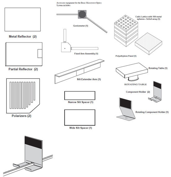
In the followings the experimental setups are demonstrated giving sketch. In the figures numbering of Fig. 5 is used.
Examination of refelection
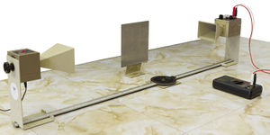
Reflection of waves is measured with goniometer using the setup shown in Fig. 6. Place the receiver on the rotating arm of the goniometer, and the metal reflector on the rotating component holder. Angle of incidence can be changed by rotating the metal reflector, reflected wave can be found by rotating the arm of the goniometer holding the receiver. Angles can be measured by using the angle scale on the goniometer.
Examination of standing waves
The sketch can be seen in Fig. 7. This exercise differs from the others as the intensity of the wave is measured by a special probe not by the receiver directly. The probe can be connected to the receiver, and its signal can be read by the instrument with indicator located on the receiver. Standing waves are generated between the transmitter and the metal reflector if their distance fulfills the condition for observing standing waves. The appropriate distance can be adjusted by moving the metal reflector. By moving the probe the position dependence of the amplitude can be measured. Knowing this and using eq. (10) the wavelength can be determined. To have better accuracy, measure the distance between the first and eleventh found maxima, not between to adjacent ones.
Refraction on a prism
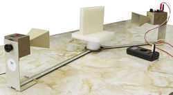
The setup is to see in Fig. 8. First study the affect of the empty prism container for the propagation of microwaves. Then fill up the prism container with styrene balls. In order to evaluate easily, rotate the prism by using the rotating table into the position in which one of the sides of the prism is perpendicular to the direction of the incident wave (Fig. 9). Find the refracted wave by rotating the arm of the goniometer holding the transmitter. The refractive index of the material filled the prism relative to the air and the speed of wave in the prism can be determined from eq. (2).
Examination of polarization
In this exercise use opposed transmitter and receiver, and for some tests place the metal grid as polarizer between them (Fig. 10a and Fig. 10b). The affect of the position of the polarizer for a polarized wave can be studied without using extra polarizer by rotating the receiver about the horizontal axis since the receiver is a polarizer, as well. With the setup the affect of the polarizer with different directions placed between the transmitter and the receiver can also be examined.
Diffraction of slit
Diffraction can be examined by using single slit and double slit according to setups in Fig. 11a and Fig. 11b. In case of double slit set 1.5 cm slit size, in case of single slit remove the middle slit spacer and use ~7 cm slit size.
Lloyd's mirror
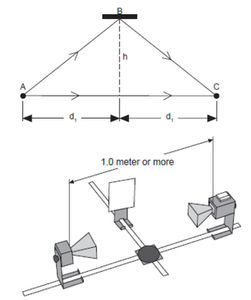
By means of Lloyd's mirror wavelength can be measured by examining the interference of waves coming from the same source but traveling different paths (paths AC and ABC in Fig. 12). In the experiment at first approach mirror B to the axis of the goniometer. The receiver detects consecutive maxima and minima depending on that the path difference in C fits to eq. (6) or eq. (7). Stop closest to the goniometer where maximum signal is observed, and measure distance  where the mirror is located. Then move away the mirror from line AC until maximal intensity is observed again, and measure distance
  of the mirror. Also if we measure the distance between the transmitter and the receiver the original path (belongs to
  ) and the new path (belongs to
  ) can be determined. In this case the path difference between the waves is
  according to eq. (6). Make sure that the axis of the transmitter and that of the receiver are located on the same straight line, and both the transmitter and the receiver are placed at the same distance from the axis of the goniometer, and the distance between them is at least 1 m. The plane of the mirror has to be parallel to the straight line between the transmitter and the receiver. Take into account the locations of effective points given in Fig. 4 when distances are being determined.
Michelson interferometer
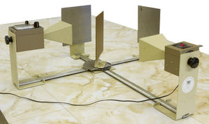
The sketch of the interferometer, which is useful for measuring wavelength and displacement, can be seen in Fig. 13. Similarly to Lloyd's mirror, wave coming from a source is divided into two parts, and they are guided in different paths then meet. At the meeting point the waves interfere, and the result (constructive or destructive interference) depends on the difference of the guided paths. In the figure a part of the wave coming from the transmitter is reflected by mirror C to mirror B, the other part goes through mirror C to mirror A. Then a part of the wave reflected by mirror B traveling through mirror C and a part of the wave reflected by mirror A being reflected by mirror C go into the receiver which detects signal according to the interference of two waves. The path difference is the difference of distances 2 BC and 2
 AC.
At first find a position of mirror A when the receiver reads maximum intensity (for the path difference condition (6) is fulfilled), then move away the mirror from mirror C until maximum signal is observed again. The distance between the two positions of mirror A is equal to
  since the path difference is
  . To measure more accurate move the mirror to a distance corresponding to 10 new maxima.
Measuring of Brewster's angle
Accomplish the measurement according to the sketch seen in Fig. 14. Set horizontal polarization for the transmitter and for the receiver (90° on the scale of their backs), rotate the polyethylene panel until the angle of incidence of the wave coming from the transmitter is about 20°. By rotating the arm of the goniometer holding the receiver find the wave reflected by the panel (maximum intensity), and record the measured intensity. In this position repeat the measurement with transmitter and receiver of vertical polarization (rotate them into 0°). Repeat this exercise with more different angle of incident. In case of Brewster's angle the horizontally polarized wave is not reflected since the vertical panel acts as a vertical polarizator for the reflected wave.
Bragg diffraction by cubic lattice
The experimental setup is shown in Fig. 15a. The task is to find the angles  according to (13) Bragg's equation in case of different vertical diffraction planes (Fig. 15b) (Three numbers indicating the diffraction planes are Miller indices of the planes. These numbers are proportional with the reciprocal of intercepts of the plane and the coordinate system parallel to the edges of the cube). Remember that the angle in eq. (13) is not the angle of incidence but it is the angle between the wave and the diffraction plane (Fig. 15c).
In case of plane (100) the following is the measuring process: Place the transmitter opposite to the receiver, and put the lattice on the rotating table in a way that the (100) planes are parallel to the direction of the incident wave, and record the intensity. Rotate the lattice by means of the rotating table by 1°, and rotate the arm of the goniometer holding the receiver by 2° clockwise. Record angle
  and the intensity. Keep rotating and measuring, and plot the intensity as a function of the angle of incidence. Maximum has to be found at angles according to Bragg's equation. By using eq. (13) distances between planes (100) can be determined. For another planes similar steps has to be taken.
Measuring tasks
- By using prism container determine the refraction index of styrene balls relative to air and the speed of wave in this medium.
- Place the transmitter opposite to the receiver in the same direction of polarization (0° on the backs of the instruments, longitudinal axes of funnels are horizontal.) Then rotate the receiver about its horizontal axis and measure how the intensity depends on the angle of the direction of the receiver (from 0° to 180°, using 10° steps). Interpret the results. In case of vertical polarization of the transmitter and the receiver (0°) place the metal grid polarizer with horizontal slit position between the transmitter and the receiver, and by rotating the receiver measure the angle dependence of the intensity. Repeat the measurement when the angle between the slits of the polarizer and the horizontal is 22,5°, 45°, 67,5° and 90°. Interpret the results. Place the transmitter and the receiver in a way that their direction of polarization is perpendicular to each other. Measure the intensity without the metal grid polarizer, then place the metal grid polarizer, and measure the intensity when the slits of the polarizer is horizontal, vertical, and at 45° with the horizontal. Interpret the results.
- Assemble the setup for measuring double slit diffraction using narrow slit spacer, and 1,5 cm slit size. Place the transmitter opposite to the receiver using vertical polarization (0°). Then by rotating the arm of the goniometer holding the receiver measure and plot how the intensity depends on the angle (between 0° and 85° using 5° steps). Verify eqs. (11), (12) (calculate the wavelength from the frequency given on the transmitter) and interpret the differences. Repeat the measurement using wide slit spacer (place the receiver at 1.5 times larger distance from the slit). Accomplish the measurement using single slit of 7 cm slit size and verify eq. (11).
- Measure the wavelength of the applied microwave with Lloyd's mirror using two different transmitter-receiver distances. Compare this result with the previous one.
- Measure the wavelength of the applied microwave with Michelson interferometer using two different initial positions of mirror A. Compare the results with each other and with previous ones.
- By using the setup for measuring Brewster's angle measure and plot the angle dependence of the intensity of the microwave reflected by the polyethylene panel. Change the angle of incidence between 20° and 75° per 5°. At first the polarization of the transmitter and the receiver is horizontal, then the polarization is vertical. Interpret the results and determine Brewster's angle.
- By using Bragg diffraction determine the distances between planes (100), (110) and (210), respectively in the given cubic lattice. Compare the results with the direct measurement of the distances.
Optional tasks (if you have time):
- Verify eq. (1) for reflecting microwaves. Change the angle of incidence between 10° and 90° per 10°. Make a table and interpret the possible deviations from the law of reflection.
- Generate standing waves, and measure the wavelength of the applied microwave. Calculate the frequency of the wave (wave of propagation is given). Accomplish the measurement using two different settings.
Important safety informations
Since the reflection of microwaves by any other objects near effects the measurement, remove every unused obejct from the table (especially metallic objects). Microwaves are reflected by the human body, as well. Never be in a position which reflects the waves coming from the transmitter to the receiver. The best option is when the measurement is done standing behind the plane of the funnel of the receiver. Although, the power of the transmitter is well below the permitted safety value, never look into the funnel of the transmitter directly when it is turned on. It may happen (but not likely) that the microwaves disturb the operation of some medical devices (for example pacemaker). If you use this kind of devices, please tell it to the instructor.
