Holography
Tartalomjegyzék |
Introduction
Humans have the ability to observe their surroundings in three dimensions. A large part of this is due to the fact that we have two eyes, and hence stereoscopic vision. The detector in the human eye - the retina - is a two-dimensional surface that detects the intensity of the light that hits it. Similarly, in conventional photography, the object is imaged by an optical system onto a two-dimensional photosensitive surface, i.e. the photographic plate. Any point, or "pixel", of the photographic plate is sensitive only to the intensity of the light that hits it, not to the entire complex amplitude (magnitude and phase) of the light wave at the given point.
Holography - invented by Dennis Gabor (1947), who received the Nobel Prize in Physics in 1971 - is different from conventional photography in that it enables us to record the phase of the light wave, despite the fact that we still use the same kind of intensity-sensitive photographic material as in conventional photography. The "trick" by which holography achieves this is to encode phase information as intensity information, and thus to make it detectable for the photographic material. Encoding is done using interference: the intensity of interference fringes between two waves depends on the phase difference between the two phase. Thus, in order to encode phase information as intensity information, we need, in addition to the light wave scattered from the object, another wave too. To make these two light waves - the "object wave" and the "reference wave" - capable of interference we need a coherent light source (a laser). Also, the detector (the photographic material) has to have a high enough resolution to be able to resolve and record the fine interference pattern created by the two waves. Once the interference pattern is recorded and the photographic plate is developed, the resulting hologram is illuminated with an appropriately chosen light beam, as described in detail below. This illuminating beam is then diffracted on the fine interference pattern that was recorded on the hologram, and the diffracted wave carries the phase as well as the amplitude information of the wave that was originally scattered from the object: we can thus observe a realistic three-dimensional image of the object. A hologram is not only a beautiful and spectacular three-dimensional image, but can also be used in many areas of optical metrology.
Theory
Recording and reconstructing a transmission hologram
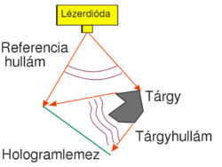
One possible holographic is shown in Fig. 1/a. This setup can be used to record a so-called off-axis transmission hologram. The source is a highly coherent laser diode that is able to produce a high-contrast interference pattern. All other light sources must be eliminated during the recording. The laser diode does not have a beam-shaping lens in front of it, and thus emits a diverging wavefront with an ellipsoidal shape. The reference wave is the part of this diverging wave that directly hits the holographic plate, and the object wave is the part of the diverging wave that hits the object first and is then scattered by the object onto the holographic plate. The reference wave and the object wave hit the holographic plate simultaneously and create an interference pattern on the plate.
The holographic plate is usually a glass plate with thin, high-resolution optically sensitive layer. The spatial resolution of holographic plates in higher by 1-2 orders of magnitude than that of photographic films used in conventional cameras. Our aim is to make the interference pattern, i.e. the so-called "holographic grating", consist of high-contrast fringes. To achieve this, the intensity ratio of the object wave and the reference wave, their total intensity, and the exposure time must all be controlled carefully. Since the exposure time can be as long as several minutes, we also have to make sure that the interference pattern does not move or vibrate relative to the holographic plate during the exposure. To avoid vibrations, the entire setup is placed on a special rigid, vibration-free optical table. Air-currents and strong background lights must also be eliminated. Note that, unlike in conventional photography or in human vision, in the setup of Fig. 1/a there is no imaging lens between the object and the photosensitive material. This also means that a given point on the object scatters light toward the entire holographic plate, i.e. there is no 1-to-1 correspondence (no "imaging") between object points and points on the photosensitive plate. This is in contrast with how conventional photography works. The setup of Fig. 1/a is called off-acis, because there is a large angle between the directions of propagation of the object wave and the reference wave.
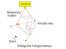
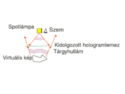
The exposed holographic plate is then chemically developed. (Note that if the holographic plate uses photopolymers then no such chemical process is needed.) Under conventional illumination with a lamp or under sunlight, the exposed holographic plate with the recorded interference pattern on it does not seem to contain any information about the object in any recognizable form. In order to "decode" the information stored in the interference pattern, i.e. in order to reconstruct the image of the object from the hologram, we need to use the setup shown in Fig. 1/b. The object itself is no longer in the setup, and the hologram is illuminated with the reference beam alone. The reference beam is then diffracted on the holographic grating. (Depending on the process used the holographic grating consists of series of dark and transparent lines ("amplitude hologram") or of a series of lines with alternating higher and lower indices of refraction ("phase hologram").) The diffracted wave is a diverging wavefront that is identical to the wavefront that was originally emitted by the object during recording. This is the so-called virtual image of the object. The virtual image appears at the location where the object was originally placed, and is of the same size and orientation as the object was during recording. In order to see the virtual image, the hologram must be viewed from the side opposite to where the reconstructing reference wave comes from. The virtual image contains the full 3D information about the object, so by moving your head sideways or up-and-down, you can see the appearance of the object from different viewpoints. This is in contrast with 3D cinema where only two distinct viewpoints (a stereo pair) is available from the scene. Another difference between holography and 3D cinema is that on a hologram you can choose different parts on the object located at different depths, and focus your eyes on those parts separately. Note, however, that both to record and to reconstruct a hologram, we need a monochromatic laser source (there is no such limitation in 3D cinema), and thus the holographic image is intrinsically monochromatic.
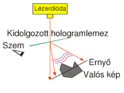
This type of hologram is called transmission hologram, because during reconstruction (Fig. 1/b) the laser source and our eye are at two opposite sides of the hologram, so light has to pass through the hologram in order to each our eye. Besides the virtual image, there is another reconstructed wave (not shown in Fig. 1/b) that is converging and can thus be observed on a screen as the real image of the object. For an off-axis setup the reconstructing waves that create the virtual and the real image, respectively, propagate in two different directions in space. In order to view the real image in a convenient way it is best to use the setup shown in Fig. 1/c. Here a sharp laser beam illuminates a small region of the entire hologram, and the geometry of this sharp reconstructing beam is chosen such that it travels in the opposite direction from what the propagation direction of the reference beam was during recording.
Theoretical background
For the case of amplitude holograms, this is how we can demonstrate that during reconstruction it is indeed the original object wave that is diffracted on the holographic grating. Consider the amplitude of the light wave in the immediate vicinity of the holographic plate. Let the complex amplitude of the two interfering waves during recording be  for the reference wave and
  for the object wave, where R and T are the amplitudes (as real numbers). The amplitude of the reference wave along the plane of the holographic plate, R(x,y), is only slowly changing, so R can be taken to be constant. The intensity distribution along the plate, i.e. the interference pattern that is recorded on the plate can be written as
![\[I_{\rm{exp}}=|\mathbf{r}+\mathbf{t}|^2 = R^2+T^2+\mathbf{rt^*+r^*t}\quad\rm{(1)}\]](/images/math/0/e/5/0e5e499a307e206fcbd6654adb0bd680.png)
 denotes complex conjugate. For an ideal holographic plate with a linear response, the opacity of the final hologram is linearly proportional to this intensity distribution, so the transmittance
  of the plate can be written as
 ![\[\tau=1–\alpha I_{\rm{exp}}\quad\rm{(2)}\]](/images/math/4/3/1/4316070b90b4e57f9bcdaba597113d90.png)
 is the product of a material constant and the time of exposure. When the holographic plate is illuminated with the original reference wave during reconstruction, the complex amplitude just behind the plate is
 ![\[\mathbf{a} = \mathbf{r}\tau=\mathbf{r}(1–\alpha R^2–\alpha T^2)–\alpha\mathbf{r}^2\mathbf{t}^*–\alpha R^2\mathbf{t}\quad\rm{(3)}\]](/images/math/d/3/8/d386e74bb76234220d62f5895d592352.png)
 , is a converging conjugate image (see
  ), and the third term, proportional t, is a copy of the original object wave (note that all proportionality constants are real!) The third term gives a virtual image, because right behind the hologram this term creates a complex wave pattern that is identical to the wave that originally arrived at the same location from the object. Equation (3) is called the fundamental equation of holography. In case of off-axis holograms the three diffraction orders (
 and
and  ) detailed above propagate in three different directions. (Note that if the response of the holographic plate is not linear then higher diffraction orders may also appear.)
Recording and reconstructing a reflection hologram
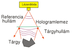
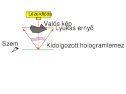
Display holograms that can be viewed in white light are different from the off-axis transmission type discussed above in two respects: (1) they are recorded in an in-line setup, i.e. both the object wave and the reference wave are incident on the holographic plate almost perpendicularly; and (2) they are reflection holograms: during recording the two waves are incident on the plate from two opposite directions, and during reconstruction illumination comes from the same side of the plate as the viewer's eye is. Fig. 2/a shows the recording setup for a reflection hologram. Figs. 2/b and 2/c show the reconstruction setup for the virtual and the real images, respectively.
The reason such holograms can be viewed in white light illumination is that they are recorded on a holographic plate on which the light sensitive layer has a thickness of at least  , much thicker than the wavelength of light. Thick diffraction gratings exhibit the so-called Bragg effect: they have a high diffraction efficiency only at or near the wavelength that was used during recording. Thus if they are illuminated with white light, they selectively diffract only in the color that was used during recording and absorb light at all other wavelengths. Bragg-gratings are sensitive to direction too: the reference wave must have the same direction during reconstruction as it had during recording. Sensitivity to direction also means that the same thick holographic plate can be used to record several distinct holograms, each with a reference wave coming from a different direction. Each hologram is then reconstructed with its own reference wave. (The thicker the material, the more selective it is in direction. A "volume hologram" can store a large number of independent images, e.g. a lot of independent sheets of binary data. This is one of the basic principles behind holographic memories.)
Holographic interferometry
Since the complex amplitude of the reconstructed object wave is determined by the original object itself, e.g. through its shape or surface quality, the hologram stores a certain amount of information about those too. If two states of the same object are recorded on the same holographic plate with the same reference wave, the resulting plate is called a "double-exposure hologram":
![\[I_{12}=|\mathbf r+\mathbf t_1|^2+|\mathbf r+\mathbf t_2|^2=R^2+T^2+\mathbf r\mathbf t_1^*+\mathbf r^*\mathbf t_1+R^2+T^2+\mathbf r\mathbf t_2^*+\mathbf r^*\mathbf t_2=2R^2+2T^2+(\mathbf r\mathbf t_1^*+\mathbf r\mathbf t_2^*)+(\mathbf r^*\mathbf t_1+\mathbf r^*\mathbf t_2)\]](/images/math/0/0/7/0078c0b66dacd94102d005e54b295c25.png)
(Here we assumed that the object wave only changed in phase between the two exposures, but its real amplitude T remained essentially the same. The lower indices denote the two states.) During reconstruction we see the two states "simultaneously":
![\[\mathbf a_{12}=\mathbf r\tau=\mathbf r(1-\alpha I_{12})=\mathbf r(1-2\alpha R^2-2\alpha T^2)-\alpha \mathbf r^2(\mathbf t_1^*+\mathbf t_2^*)+\alpha R^2(\mathbf t_1+\mathbf t_2)\]](/images/math/8/7/d/87ddc9647964e179953751d45f3d011d.png)
i.e. the wave field  contains both a term proportional to
  -el and a term proportional to
  in both the first and the minus first diffraction orders. If we view the virtual image, we only see the contribution of the last terms
  , since all the other diffraction orders propagate in different directions than this. The observed intensity in this diffraction order, apart from the proportionality factor
  , is:
, is:
![\[I_{12,\text{virt}}=|\mathbf a_{12,\text{virt}}|^2=|\mathbf t_1+\mathbf t_2|^2=2T^2+(\mathbf t_1^* \mathbf t_2+\mathbf t_1 \mathbf t_2^*)=2T^2+(\mathbf t_1^* \mathbf t_2+c.c.)\]](/images/math/9/4/f/94f5caf469c66f3743dd11c3b159cc5f.png)
 and
and  ,
, ![\[\mathbf t_1^*\mathbf t_2=T^2e^{i[\varphi_2(x,y)-\varphi_1(x,y)]},\]](/images/math/1/d/a/1da9f8fae36674a1795aeb6b666ca89a.png)
![\[2T^2\cos[\varphi_2(x,y)-\varphi_1(x,y)]\]](/images/math/c/5/2/c524dd642789e50faaf392bad825e5de.png)
 and
and  that determine the interference fringes, you can show that their difference can be written as
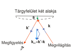
 ![\[\Delta\varphi=\varphi_2-\varphi_1=\vec s\cdot(\vec k'-\vec k)=\vec s\cdot\vec k_\text{sens}\quad\rm{(9)}\]](/images/math/1/2/1/121fb8e08c10a6fd6cde08dae0a1cc16.png)
 is the wave vector of the plane wave that illuminates the object,
  is the wave vector of the beam that travels from the object toward the observer (
 ),
),  is the displacement vector, and
  is the so-called "sensitivity vector". The red arrows in the figure represent arbitrary rays from the expanded beam. Since in a general case the displacement vector is different on different parts of the surface, the phase difference will be space-variant too. We can see from the scalar product that it is only the component of
  that lies along the direction of the sensitivity vector that "can be measured". Both the direction and the length of the sensitivity vector can be changed by controlling the direction of the illumination or the direction of the observation (viewing). This also means that e.g. if we move our viewpoint in front of a double-exposure hologram, the phase difference, and thus the interference fringes, will change too.
We can observe the same kind of fringe pattern if we first make a single exposure hologram of the object, next we place the developed holographic plate back to its original position within a precision of a few tenths of a micron (!), and finally we deform the object while still illuminating it with the same laser beam that we used during recording. In this case the holographically recorded image of the original state interferes with the "live" image of the deformed state. In this kind of interferometry, called the "real-time holographic interferometry", we can change the deformation and observe the corresponding change in the fringe pattern in real time.
Holographic optical elements
If both the object wave and the reference wave are plane waves and they subtend a certain angle, the interference fringe pattern recorded on the hologram will be a simple grating that consists of straight equidistant lines. This is the simplest example of "holographic optical elements" (HOEs). Holography is a simple technique to create high efficiency dispersive elements for spectroscopic applications. The grating constant is determined by the wavelength and angles of incidence of the two plane waves, and can thus be controlled with high precision. Diffraction gratings for more complex tasks (e.g. gratings with space-variant spacing, or focusing gratings) are also easily made using holography: all we have to do is to replace one of the plane waves with a beam having an appropriately designed wavefront.
Since the reconstructed image of a hologram shows the object "as if it were really there", by choosing the object to be an optical device such as a lens or a mirror, we can expect the hologram to work, with some limitations, like the optical device whose image it recorded (i.e. the hologram will focus or reflect light in the same way as the original object did). Such simple holographic lenses and mirrors are further examples of HOEs.
As an example, let's see how, by recording the interference pattern of two simple spherical waves, we can create a "holographic lens". Let's suppose that both spherical waves originate from a point that lies on the optical axis which is perpendicular to the plane of the hologram. (This is a so-called on-axes arrangement.) The distance between the hologram and one spherical wave source (let's call it the reference wave) is , and the distance of the hologram from the other spherical wave source (let's call it the object wave) is
  . Using the well-known parabolic/paraxial approximation of spherical waves, and assuming both spherical waves to have unit amplitudes, the complex amplitudes
  and.
and.  of the reference wave and the object wave, respectively, in a point (x,y) on the holographic plate can be written as
 ![\[\mathbf r=e^{i\frac{2\pi}{\lambda}\left(\frac{x^2+y^2}{2f_1}\right)},\,\mathbf t=e^{i\frac{2\pi}{\lambda}\left(\frac{x^2+y^2}{2f_2}\right)}\quad\rm{(10)}\]](/images/math/1/7/0/1706a6214a80fea2bb97548d644aa4c3.png)
The interference pattern recorded on the hologram becomes:
![\[I=2+e^{i\frac{2\pi}{\lambda}\left(\frac{x^2+y^2}2\left( \frac 1{f_2}-\frac 1{f_1}\right)\right)}+e^{-i\frac{2\pi}{\lambda}\left(\frac{x^2+y^2}2\left( \frac 1{f_2}-\frac 1{f_1}\right)\right)}\quad\rm{(11)}\]](/images/math/3/b/8/3b841288512c58c73b684f4ad7b370b6.png)
and the transmittance  of the hologram can be written again using equation (2), i.e. it will be a linear function of
  . Now, instead of using the reference wave
  , let's reconstruct the hologram with a "perpendicularly incident plane wave" (i.e. with a wave whose complex amplitude in the plane of the hologram is a real constant
  ). This will replace the term
  with the term
  in equation (3), i.e. the complex amplitude of the reconstructed wave just behind the illuminated hologram will be given by the transmittance function
  itself (ignoring a constant factor). This, together with equations (2) and (11) show that the three reconstructed diffraction orders will be:
- a perpendicular plane wave with constant complex amplitude (zero-order),
- a wave with a phase
 (+1st order),
- a wave with a phase
 (-1st order).
We can see from the mathematical form of the phases of the  -orders (reminder: formulas (10)) that these two orders are actually (paraxial) spherical waves that are focused at a distance of
  and
and  from the plane of the hologram, respectively. One of
  and
and  is of course positive and the other is negative, so one diffraction order is a converging spherical wave and the other a diverging spherical wave, both with a focal distance of
  . In summary: by holographically recording the interference of two on-axis spherical waves, we created a HOE that can act both as a "concave" and as a "convex" lens, depending on which diffraction order we use in a given application.
The most important application of HOEs is when we want to replace a complicated optical setup that performs a complex task (e.g. multifocal lenses used for demultiplexing in optical telecommunications) with a single compact hologram. In such cases holography can lead to a significant reduction in size and cost.
Digital holography
Almost immediately after conventional laser holography was developed in the 1960's, scientists became fascinated by the possibility to treat the interference pattern between the reference wave and the object wave as an electronic or digital signal. This either means that we take interference field created by two actually existing wavefronts and store it digitally, or that we calculate the holographic grating pattern digitally and then reconstruct it optically.
The major obstacles that had hindered the development of digital holography for a long time were the following:
- In order to record the fine structure of the object wave and the reference wave, one needs an image input device with a high spatial resolution (at least 100 lines/mm), a high signal-to-noise ratio, and high stability.
- To treat the huge amount of data stored on a hologram requires a large computational power.
- In order to reconstruct the wavefronts optically, one needs a high resolution display.
The subfield of digital holography that deals with digitally computed interference fringes which are then reconstructed optically, is nowadays called "computer holography". The other subfield of digital holography - the one that involves the digital storage of the interference field between physically existing wavefronts - underwent significant progress in the past few years, thanks in part to the spectacular advances in computational power, and in part to the appearance of high resolution CCD and CMOS cameras. On the other hand, spatial light modulators (SLM's) enable us to display a digitally stored holographic fringe pattern in real time. Digital holography has reached a level where we can begin to use it in optical metrology.
Note that there is no fundamental difference between conventional optical holography and digital holography: both share the basic principle of coding phase information as intensity information.
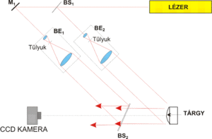
To record a digital hologram, one basically needs to construct the same setup, shown in Fig. 4, that was used in conventional holography. The setup is a Mach-Zehnder interferometer in which the reference wave is formed by passing part of the laser beam through beamsplitter BS1, and beam expander and collimator BE1. The part of the laser beam that is reflected in BS1 passes through beam expander and collimator BE2, and illuminates the object. The light that is scattered from the object (object wave) is brought together with the reference wave at beamsplitter BS2, and the two waves reach the CCD camera together.
The most important difference between conventional and digital holography is the difference in resolution between digital cameras and holographic plates. While the grain size (the "pixel size") of a holographic plate is comparable with the wavelength of visible light, the pixel size of digital cameras is typically one order of magnitude larger, i.e. 4-10 µm. The sampling theorem is only satisfied if the grating constant of the holographic grating is larger than the size of two camera pixels. This means that both the viewing angle of the object as viewed from a point on the camera and the angle between the object wave and reference wave propagation directions must be smaller than a critical limit. In conventional holography, as Fig. 1/a shows, the object wave and the reference wave can make a large angle, digital holography - due to its much smaller spatial resolution - only works in a quasi in-line geometry. A digital camera differs from a holographic plate also in its sensitivity and its dynamic range (signal levels, number of grey levels), so the circumstances of exposure will also be different in digital holography from what we saw in conventional holography above.
As is well-known, the minimum spacing of an interference fringe pattern created by two interfering plane waves is  , where
  is the angle between the two propagation directions. Using this equation and the sampling theorem, we can specify the maximum angle that the object wave and the reference wave can make:
  , where
  is the pixel size of the camera. For visible light and today's digital cameras this angle is typically around
  , hence the in-line geometry shown in Fig. 4.
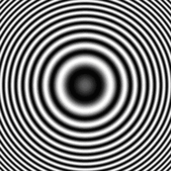
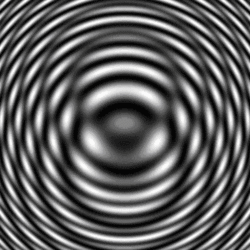
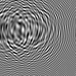
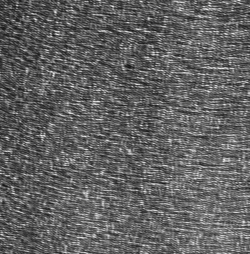
Figure 5 illustrates the appearance of digital holograms. Figs 5/a-c show computer simulated holograms, and Fig. 5/d shows the digital hologram of a real object, recorded in the setup of Fig. 4.
For the numerical reconstruction of digital holograms ("digital reconstruction") we simulate the optical reconstruction of analog amplitude holograms on the computer. If we illuminate a holographic plate (a transparency that introduces amplitude modulation) with a perpendicularly incident plane reference wave, in "digital holography language" this means that the digital hologram can directly be regarded as the amplitude of the wavefront, while the phase of the wavefront is constant. If the reference wave was a spherical wave, the digital hologram has to have the corresponding (space-variant) spherical wave phase, so the wave amplitude at a given pixel will be a complex number.
Thus we have determined the wavefront immediately behind the virtual holographic plate. The next step is to simulate the "propagation" of the wave. Since the physically existing object was at a finite distance from the CCD camera, the propagation has to be calculated for this finite distance too. Since there was no lens in our optical setup, we have to simulate free-space propagation, i.e. we have to calculate a diffraction integral numerically. From the relatively low resolution of the CCD camera and the small propagation angles of the waves we can immediately see that we can apply the parabolic/paraxial Fresnel approximation. This is a great advantage, because the calculation can be reduced to a Fourier transform. In our case the Fresnel approximation of diffraction can be written as
![\[A(u,v)=\frac{i}{\lambda D}e^{\frac{-i\pi}{\lambda D}(u^2+v^2)}\int_{\infty}^{\infty}\int_{\infty}^{\infty}R(x,y)h(x,y) e^{\frac{-i\pi}{\lambda D}(x^2+y^2)}e^{i2\pi(xu+yv)}\textup{d}x\textup{d}y,\]](/images/math/a/f/4/af45dae0275f89c2b7b88949029ea181.png)
 is the complex amplitude distribution of the result (the reconstructed image) - note that this implies a phase information too! -,
  is the digital hologram,
  is the complex amplitude of the reference wave,
  is the distance of reconstruction/object/image from the hologram (from the CCD camera), and
  is the wavelength of light. Using the Fourier transform and switching to discrete numerical coordinates, the expression above can be rewritten as
 ![\[A(u',v')=\frac{i}{\lambda D}e^{\frac{-i\pi}{\lambda D}\left((u'\Delta x')^2+(v'\Delta y')^2\right)}\mathcal F^{-1} \left[R(x,y)h(x,y) e^{\frac{-i\pi}{\lambda D}\left((k\Delta x)^2+(l\Delta y)^2\right)}\right],\]](/images/math/4/b/5/4b50a83f1598f3e0c4d8a9de93e5f26a.png)
We can see that, except for the reconstruction distance D, all the parameters of the numerical reconstruction are given. Distance D, however can - and, in case of an object that has depth, should - be changed relatively freely, around the value of the actual distance between the object and the camera. Hence we can see a sharp image of the object in the intensity distribution formed from the A(u,v). This is similar to adjusting the focus in conventional photography in order to find a distance where all parts of the object look tolerably sharp. We note that the Fourier transform uniquely fixes the pixel size Δx′, Δy′ in the (u,v) image plane according to the formula  where
where  is the (linear) matrix size in the
  direction used in the fast-Fourier-transform-algorithm. This means that the pixel size on the image plane changes proportionally to the reconstruction distance D. This effect must be considered if one wants to interpret the sizes on the image correctly.
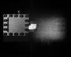
The figure below shows the computer simulated reconstruction of a digital hologram that was recorded in an actual measurement setup. The object was a brass plate (membrane) with a size of 40 mm x 40 mm and a thickness of 0.2mm that was fixed around its perimeter. To improve its reflexivity the object was painted white. The speckled appearance of the object in the Figure is not caused by the painting, but is an unavoidable consequence of a laser illuminating a matte surface. This is a source of image noise in any such measurement. The Figure shows not only the sharp image of the object, but also a very bright spot at the center and a blurred image on the other side of it. These three images are none other than the three diffraction orders that we see in conventional holography too. The central bright spot is the zero-order, the minus first order is the projected real image (that is what we see as the sharp image of the object), and the plus first order corresponds to the virtual image. If the reconstruction is calculated in the opposite direction at a distance -D, what was the sharp image becomes blurred, and vice versa, i.e. the plus and minus first orders are conjugate images, just like in conventional holography.
A digital hologram stores the entire information of the complex wave, and the different diffraction orders are "separated in space" (i.e. they appear at different locations on the reconstructed image), thus the area where the sharp image of the object is seen contains the entire complex amplitude information about the object wave. In principle, it is thus possible to realize the digital version of holographic interferometry. If we record a digital hologram of the original object, then deform the object, and finally record another digital hologram of its deformed state, all we need to perform holographic interferometry is digital data processing.
In double-exposure analog holography it would be the sum, i.e. the interference, of the two waves (each corresponding to a different state of the object) that would generate the contour lines of the displacement field, so that is what we have to simulate now. We numerically calculate the reconstruction of both digital holograms in the appropriate distance and add them. Since the wave fields of the two object states are represented by complex matrices in the calculation, addition is done as a complex operation, point-by-point. The resultant complex amplitude distribution is then converted to an intensity distribution which will display the interference fringes. Alternatively, we can simply consider the phase of the resultant complex amplitude distribution, since we have direct access to it. If, instead of addition, the two waves are subtracted, the bright zero-order spot at the center will disappear.
Speckle pattern interferometry, or TV holography
If a matte diffuser is placed in the reference arm at the same distance from the camera as the object is, the recorded digital hologram is practically impossible to reconstruct, because we don't actually know the phase distribution of the diffuse reference beam in the plane of the camera, i.e. we don't know the complex function R(x,y). If, however, we place an objective in front of the camera and adjust it to create a sharp image of the object, we don't need the reconstruction step any more. What we have recorded in this case is the interference between the object surface and the diffusor as a reference surface. Since each image in itself would have speckles, their interference has speckles too, hence the name "speckle pattern interferometry". Such an image can be observed on a screen in real time (hence the name "TV holography"). A single speckle pattern interferogram in itself does not show anything spectacular. However, if we record two such speckle patterns corresponding to two states of the same object - similarly to double-exposure holography -, these two images can be used to retrieve the information about the change in phase. To do this, all we have to do is to take the absolute value of the difference between the two speckle pattern interferograms.
Measurement tasks
Making a reflection (or display) hologram
In the first part of the lab, we record a white-light hologram of a strongly reflecting, shiny object on a holographic plate with a size of appr.  . The light source is a red laser diode with a nominal power of
  and a wavelength of
  that is connected to a
  battery and takes a current of appr.
  . It is a "bare" laser diode (with no collimating lens placed in front of it), so it emits a diverging beam. The holographic plates are LITIHOLO RRT20 plates: they are glass plates coated with a photosensitive layer that contains photopolymer emulsion and is sensitive to the wavelength range ~500-660 nm. In order to expose the RRT20 plate properly at
  , we need an (average) energy density of at least
  . There is practically no upper limit to this energy density. The emulsion has an intensity threshold below which it gives no response to light at all, so we can use a weak scattered background illumination throughout the measurement. The photosensitive layer has a thickness of
  , much larger than the illuminating wavelength, i.e. it can be used to record volume holograms (see the explanation on Bragg diffraction above). During exposure the intensity variations of the illumination are encoded in the instant film as refractive index modulations in real time. One of the main advantages of this type of holographic plates is that they don't require
Ennek az anyagnak az egyik fő előnye, hogy exponálás után semmilyen, a hagyományos holografikus emulziók esetén használatos kémiai eljárást (előhívás, halványítás, rögzítés), vagy más fotopolimereknél szükséges UV illetve hőkezelést nem igényel, mivel a holografikus rács a beírás folyamán végleges formájában rögzül az anyagban. A hologramlemezek fényzáró dobozban találhatók, melyet csak gyenge háttérfény esetén, közvetlenül az exponálás előtt szabad kinyitni, majd egy lemezt kiemelve rögtön visszazárni.
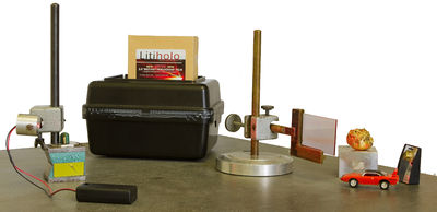
Állítsa össze a 2/a. ábra elrendezését az optikai asztalon látható felnyitható tetejű fadoboz belsejében, és dokumentálja a ténylegesen használt elrendezést lehetőleg digitális fénykép készítésével, vagy megfelelő eszköz hiányában méretarányos rajzzal, mely nagyságrendileg szöghelyes és rajta a jellemző távolságok is fel vannak tüntetve. Az elemek egy része mágneses talpakon található, melyeket forgatógombbal lehet lazítani illetve rögzíteni. A többi állítási lehetőséget a szárnyas anyát használó befogások jelentik. Használja a mérőhelyen található próbalemezt és azonos méretű papírt a beállításhoz, a nyaláb követéséhez. Helyezze a tárgyat egy hasábra a megfelelő magasság eléréséhez. A lemezt speciális tartóba lehet helyezni, mely csavarokkal szorítja a lemezt a helyére. Ellenőrizze, hogy a lemez majdnem teljes felülete és a tárgy megfelelő oldala is elegendően nagy felületen árnyékmentesen meg van világítva. Helyezze a tárgyat és a lemezt a lehető legközelebb egymáshoz. Segíti a későbbi rekonstrukciót, ha a megvilágítás valamennyire ferdén felülről érkezik a függőleges helyzetű lemezre. A lemez egyik oldalán található a fényérzékeny fólia, ennek célszerű a tárgy felőli oldalra kerülnie. Ellenőrizze, hogy a rögzítések megfelelőek, nincs-e „nyitva” hagyott mágneses talp, vagy laza szárnyas anya.
Exponálás előtt mutassa meg az elrendezést a mérésvezetőnek. Jóváhagyás után megkezdődhet az exponálás. Ehhez kapcsolja le a szoba mennyezeti fénycsöveit, eressze le majdnem teljesen a sötétítőket, kapcsolja le a lézert (tápegységen output off), majd vegyen ki egy lemezt a tartódobozból, és azt zárja vissza. Fogja be a lemezt a tartóba, majd fél perces várakozást követően kapcsolja vissza a lézert. Az exponálás időtartamára az anyag viselkedése miatt szintén minimumfeltétel vonatkozik, ez kb. 5 perc. Exponálás közben a lemez átlátszósága megnövekszik, mivel a kiépülő hologram rekonstruált képe egyre több fényt juttat a tárgyra, így az exponálás folyamata élőben is "követhető", illetve megállapítható a vége. Ha bizonytalan az időt illetően, inkább exponáljon tovább 2 perccel. A hologram készítése közben kerülni kell a zavaró fényeket, mozgást és rezgést, így a többi mérőcsoport figyelmét is fel kell hívni a megfelelő viselkedésre.
Exponálás után vegye ki a helyéről a tárgyat, és a lézer fényében figyelje meg a rekonstruált virtuális képet. Ezután vegye ki a tartóból a hologramot, és a laborban található színes és fehér nagyteljesítményű LED-ek fényében is rekonstruálja a virtuális képet. Milyen színben látható fehér LED esetén a tárgy virtuális képe? És ha nagyon ferdén nézzük és világítjuk meg? Mi látható, ha a lemezt az oldalán átfordítva nézzük? Jegyezze fel tapasztalatait, és lehetőleg dokumentálja a látottakat (akár utólag otthon) digitális fényképpel is!
Megjegyzés: Az előbbi feladathoz saját tárgyakat is lehet hozni, de rendelkezünk jól bevált tárgykészlettel. Alkalmas tárgyak: érmék, kulcsok, fém dísztárgyak (méretkorláttal), és arany vagy ezüst festékkel csillogóra festett egyéb tárgyak, macskaszem prizma. Korlátozottan alkalmasak fehér, sima felületű tárgyak, kis plüssfigurák (rövid szőrrel), fehér LEGO elemek.
Elmozdulásmező vizsgálata real-time holografikus interferometriával reflexiós elrendezésben
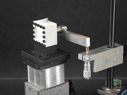
Az előző mérési feladattal lényegében megegyező elrendezést kell itt is használni, mindössze a tárgyat kell kicserélni a laborban található középen megnyomható membránra, és annak felületére merőleges megvilágításra van szükség. A merőlegességet a (9) képlet alkalmazásánál fogjuk felhasználni. A membrán közepét egy mikrométerorsó nyomja, mely  mikronos osztású, és
  egy fordulata. Ezt az orsót egy hozzá rögzített karon keresztül forgatjuk, melynek végét egy ugyanilyen orsó mozgatja. Mérje meg, hogy milyen hosszú a „külső“ orsó karja, azaz hol érinti azt a „belső“ orsó tengelyétől számítva, és határozza meg, hogy a külső orsó egy fordulata mennyivel nyomja meg a membrán közepét. A kar általában úgy van ráerősítve a "belső" mikrométer orsóra, hogy a kar mozgatásakor az már felütközik a membrán belső felületén. Hogy ez tényleg így van, vagy valamilyen hallgatói beavatkozás miatt mégsem, arról úgy lehet megyőződni, hogy a membrán felüleltén lézeres megvilágítás esetén látható úgynevezett lézerszemcsék a kar mozgatásakor radiális mozgást végeznek-e vagy sem.
A real-time interferogram készítéséhez a membránról reflexiós hologramot kell készíteni az előző mérési feladattal megegyező módon. Ezután nem szabad semmit el- vagy megmozdítani a külső orsó kivételével! Mivel a holografikus rács már ilyenkor is diffraktál, a membránt részben a referencia és részben a tárgyhullám világítja meg (azaz a saját virtuális képe). Továbbra is sötétben lassan tekerjen a külső orsón néhány egész fordulatot, és közben figyelje a membrán felületét a hologramlemezen keresztül. A növekvő deformációval egyre sűrűbb csíkrendszer áll elő, amely a membrán alap és deformált állapota közötti interferencia eredményeképp jön létre. Ez a real-time interferogram. Két-három különböző mértékben benyomott állapotban rögzítse az orsó tekeréseinek számát, és számlálja le a hozzá tartozó csíkszámot a membrán felületén  csík pontossággal, majd a mérés kontúrtávolságával (lásd korábbi interferométeres mérések) szorozva állapítsa meg a membrán közepén fellépő legnagyobb elmozdulás névleges(mikrométerről leolvastható) és mért (interferogramról leolvasható) értékeit. Ha a leolvasások végeztével kicsit elmozdítja akár a tárgyat, akár a hologramlemezt, mit tapasztal? Mit árul el a csíkok alakja az elmozdulásmezőről? Értelmezze a látottakat. (Megj.: Ha a feladat végeztével az edereti tárgy nélküli rekonstrukciókor látható valamilyen kétexpozíciós csíkrendszer a virtuális tárgyfelületen, arról a látványról is érdemes fényképet készíteni a jegyzőkönyv számára.)
Holografikus optikai elem készítése
Ismételje meg az első feladatot tárgyként a mérőhelyen található domború tükröt használva. Vizsgálja meg a kész holografikus tükör működését, és jegyezze fel tapasztalatait. Hogyan jelenik meg a domború tükörnek megfelelő tükörkép? Hogyan viselkedik az optikai elemünk, ha a másik oldalát használjuk? Mi változik, ha a beeső fénysugarak és a megfigyelés is ferdék? Lehetséges valós, vetített képet készíteni az elemmel? Használja a mérőhelyen található piros és fehér LED fényforrásokat, vagy egy mobiltelefon vakuzó LED-jét folytonos üzemben. Lehetőség szerint dokumentálja is a látottakat digitális fényképekkel.
Transzmissziós hologram készítése
Állítson össze transzmissziós hologram elrendezést az 1/a. ábra szerint, és dokumentálja azt az első feladathoz hasonlóan. Ellenőrizze, hogy a lemez helyéről mi látszik a tárgyból, illetve hogy szóródik-e róla fény a lemez felé. Törekedjen arra, hogy a referencia és a tárgynyaláb egymással bezért szöge 30-45 fok körül legyen, valamint az úthosszak különbsége se legyen 10 centinél sokkal nagyobb. A lemezt úgy kell a tartóba helyezni, hogy a fóliázott rész a beérkező nyalábok felé nézzen. Az exponálást az első feladatban leírtaknak megfelelően kell végezni. A kész hologram csak lézerfényben tekinthető meg. Nézze meg az eredményt az 1/b. és az 1/c. ábrák elrendezésében is, utóbbihoz egy másik, nem táguló nyalábú lézer szükséges. Hogyan jelenik meg a holografikus kép térbelisége? Működhet-e a rekonstrukció más színű lézerrel? Lehetőség szerint készítsen digitális fényképet a rekonstrukciókor látottakról.
Elmozdulásmező vizsgálata digitális holográfiával
A mérési gyakorlat második részében megmérjük egy membrán közepén a síkra merőleges elmozdulás legnagyobb értékét. A méréshez a 4. ábrán látható elrendezést használjuk, de a valóságos kitágított nyalábjaink nem tökéletes síkhullámok. A fényforrás egy 35 mW teljesítményű 632,8 nm-es vörös fényű léghűtéses He-Ne gázlézer. A képeket egy Baumer Optronics MX13 típusú 1280x1024 képpont felbontású monokróm CCD kamerával rögzítjük, melynek képpontmérete 6,7 μm x 6,7 μm, és saját kezelőprogrammal rendelkezik. Ebben a kamera élőképe is megtekinthető (jobb oldalon a kék film gomb, a szürke azonnali lefagyást okoz!), valamint kézzel állíthatók az exponálás (záridő, erősítés) paraméterei a távcső ikonnal ellátott gomb alatti gombbal. Az erősítés optimális értéke 100-120 körüli az állító csúszka középső tartományában. A rögzített 8 bites színmélységű kép hisztogramja (különböző szürkeségi szintű pixelek számának eloszlása) egy másik programmal tekinthető meg. Ebben a Hisztogram gombra kattintva a mintavevő ablak a címsorát egérrel elhúzva a megfelelő képterületre helyezhető, majd dupla kattintással rögzül. Ezután a Timer gombbal ki/be kapcsolható a hisztogram élő követése. A hisztogram ábra és a felette található limitszámlálók értéke alapján állapítható meg pontosan, hogy a kép esetleg alul- vagy túlexponált. (A hisztogram funkció számos digitális fényképezőgépben is megtalálható már.) Az elrendezésben található BS1 nyalábosztó forgatható, ezáltal az intenzitás osztásaránya változtatható a tárgy- és a referenciaág között, de a referenciaágban található még egy forgatható nyalábosztó, amelyet további gyengítésre használunk. A digitális hologramokat egy HoloVision 2.2 nevű szabadon felhasználható programmal rekonstruáljuk (projekt honlap).
A tényleges mérés előtt ellenőrizzük az elrendezést és annak beállításait. Mérje meg a kamera és a tárgy távolságát. Az elrendezésben a megfigyelés merőleges a membrán felületére, a megvilágítás azonban nem. Mérje meg ennek szögét távolságokból, és az adatok alapján a (9) összefüggés alkalmazásával határozza meg azt a síkra merőleges elmozdulásértéket, amelynél az okozott fázisváltozás 2π. (Ehhez vegyen fel egy derékszögű koordinátarendszert a membránhoz igazodva.) Ez lesz a mérés ún. kontúrtávolsága, azaz lényegében alapvető nagyságrendje.
Ellenőrizze a rögzíthető képek exponáltságát kitakart referencia és tárgynyaláb esetén, valamint kitakarás nélkül. Szükség esetén állítson az expozíció paraméterein és a forgatható nyalábosztókon: se a tárgynyaláb, se a referencianyaláb ne legyen önmagában túl sötét, az interferenciaképük viszont ne legyen túl világos. Figyelje meg, mi látható a kamera élőképén, ha a BS2 osztótükröt finoman rezgetjük? Hogyan néz ki a kép hisztogramja megfelelő beállítások esetén?
Ha az exponálás már megfelelő, vegyen fel egy képet, és rekonstruálja azt a HoloVisionnel (Image/Reconstruct menüparancs). A digitális hologram hisztogramját és az expozíció paramétereit vegye bele a jegyzőkönyvbe. Értékelje a rekonstrukció intenzitásképének élességét a rögzítőkeret membránra vetett árnyéka alapján. Vizsgálja meg az élesség változását 5-10 centivel kisebb illetve nagyobb rekonstrukciós távolságok esetén. Hol a legélesebb a kép? Eltér ez a távolság a ténylegesen mérttől, ha igen vajon miért? Mekkora a képpontméret ebben a távolságban? Mennyire egyezik a képről leolvasható tárgyméret a valóságossal?
Vegyen fel egy hologramot a membránról, majd deformálja azt 5 μm-nél kisebb mértékben a hátulján található csavarmikrométerhez csatlakoztatott szerkezet segítségével (lásd a mérés első részében használt áttételezést) . Vegyen fel még egy képet. Adja össze a két hologramot (Image/Calculations menüparancs), majd rekonstruálja az összeget. Mi látható az intenzitásképen? Az eredményt mellékelje a jegyzőkönyvbe is. Most az összeg helyett rekonstruálja a különbséget. Miben tér el az intenzitáskép az előzőtől? A csíkrendszer kvalitatíve mit árul el az elmozdulásmezőről? Értelmezze a látottakat. Számlálja le a csíkokat a membrán szélétől a közepéig  csík pontossággal, majd a mérés kontúrtávolságával szorozva állapítsa meg a legnagyobb elmozdulást (megnyomást). Vesse össze a mikrométerről „névlegesen” leolvasható értékkel.
Ha megfelelő interferogramokat kapott, térjen át a következő feladatra, szemcsekép interferogram készítésére. Csavarja rá a kamerára az ott található foto-objektívet, majd helyezze el a diffúzort a referencia nyaláb útjába úgy, hogy a kamera azonos távolságban érzékelje, mint a tárgyat. Állítsa élesre a tárgyon a keret önárnyékának képét kis rekeszérték (f/2.8) és így kis mélységélesség mellett. A rekeszállító gyűrű lépcsőzetes működésű. Ha a kép kellően éles, akkor nagy, f/16-os rekeszérték mellett a tárgy deformációjakor a rajta látható lézerszemcsék nem mozognak, csak a fényességük változik. Ha ez sikerült, végül állítsa f/16-os értékre a rekeszt. Az osztótükör és a referencia ágban található gyengítő forgatásával érje el, hogy a tárgyfelület és a diffúzor képe azonos fényességűnek látszódjon. Rögzítsen egy-egy szemcseképet a tárgy kétféle terhelési állapotában, majd képezze ezek különbségét a Holovisionnel, és jelenítse meg ennek "Modulus"-át, azaz abszolút értékét. Mit lát a képen? Hogyan értelmezhetők a látottak? Vajon miért nem ad hasonló eredményt a szemcseképek összegzése is, mint digitális holográfia esetén?
Egyéb információk
A jegyzőkönyvben: elméleti bevezető nem szükséges, de saját igény esetén se legyen több egy oldalnál. Foglalja össze a mérés során tapasztaltakat! Mellékelje a ténylegesen használt elrendezések rajzát vagy fényképét, és ha készültek digitális fényképek a rekonstrukciókról, azokat is. Térjen ki a mérési feladatokban megfogalmazott kérdésekre is!
Biztonsági tudnivalók: A direkt lézerfénybe ne nézzünk bele, különösen a digitális holográfia résznél használtba! A nem kitágított vagy nem szórt lézerfénnyel megvilágított pontokat lehetőleg ne nézzük hosszabb ideig, a szórt lézerfénybe pedig csak a szükséges ideig nézzünk! A csillogó ékszereket vagy karórákat vegyük le, az optikai asztalok magasságába ne hajoljunk le! Mozogjunk körültekintően a laborban: vigyázzunk az asztal széléhez közel lévő beállított elemekre, illetve a nyalábtágítókig található elemekre!
Linkek:
