Holography
Tartalomjegyzék |
Introduction
Humans have the ability to observe their surroundings in three dimensions. A large part of this is due to the fact that we have two eyes, and hence stereoscopic vision. The detector in the human eye - the retina - is a two-dimensional surface that detects the intensity of the light that hits it. Similarly, in conventional photography, the object is imaged by an optical system onto a two-dimensional photosensitive surface, i.e. the photographic plate. Any point, or "pixel", of the photographic plate is sensitive only to the intensity of the light that hits it, not to the entire complex amplitude (magnitude and phase) of the light wave at the given point.
Holography - invented by Dennis Gabor (1947), who received the Nobel Prize in Physics in 1971 - is different from conventional photography in that it enables us to record the phase of the light wave, despite the fact that we still use the same kind of intensity-sensitive photographic material as in conventional photography. The "trick" by which holography achieves this is to encode phase information as intensity information, and thus to make it detectable for the photographic material. Encoding is done using interference: the intensity of interference fringes between two waves depends on the phase difference between the two phase. Thus, in order to encode phase information as intensity information, we need, in addition to the light wave scattered from the object, another wave too. To make these two light waves - the "object wave" and the "reference wave" - capable of interference we need a coherent light source (a laser). Also, the detector (the photographic material) has to have a high enough resolution to be able to resolve and record the fine interference pattern created by the two waves. Once the interference pattern is recorded and the photographic plate is developed, the resulting hologram is illuminated with an appropriately chosen light beam, as described in detail below. This illuminating beam is then diffracted on the fine interference pattern that was recorded on the hologram, and the diffracted wave carries the phase as well as the amplitude information of the wave that was originally scattered from the object: we can thus observe a realistic three-dimensional image of the object. A hologram is not only a beautiful and spectacular three-dimensional image, but can also be used in many areas of optical metrology.
Theory
Recording and reconstructing a transmission hologram
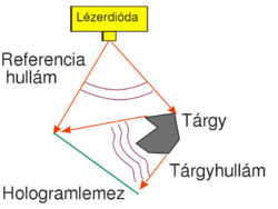
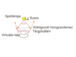
One possible holographic is shown in Fig. 1/a. This setup can be used to record a so-called off-axis transmission hologram. The source is a highly coherent laser diode that is able to produce a high-contrast interference pattern. All other light sources must be eliminated during the recording. The laser diode does not have a beam-shaping lens in front of it, and thus emits a diverging wavefront with an ellipsoidal shape. The reference wave is the part of this diverging wave that directly hits the holographic plate, and the object wave is the part of the diverging wave that hits the object first and is then scattered by the object onto the holographic plate. The reference wave and the object wave hit the holographic plate simultaneously and create an interference pattern on the plate.
The holographic plate is usually a glass plate with thin, high-resolution optically sensitive layer. The spatial resolution of holographic plates in higher by 1-2 orders of magnitude than that of photographic films used in conventional cameras. Our aim is to make the interference pattern, i.e. the so-called "holographic grating", consist of high-contrast fringes. To achieve this, the intensity ratio of the object wave and the reference wave, their total intensity, and the exposure time must all be controlled carefully. Since the exposure time can be as long as several minutes, we also have to make sure that the interference pattern does not move or vibrate relative to the holographic plate during the exposure. To avoid vibrations, the entire setup is placed on a special rigid, vibration-free optical table. Air-currents and strong background lights must also be eliminated. Note that, unlike in conventional photography or in human vision, in the setup of Fig. 1/a there is no imaging lens between the object and the photosensitive material. This also means that a given point on the object scatters light toward the entire holographic plate, i.e. there is no 1-to-1 correspondence (no "imaging") between object points and points on the photosensitive plate. This is in contrast with how conventional photography works. The setup of Fig. 1/a is called off-acis, because there is a large angle between the directions of propagation of the object wave and the reference wave.
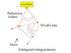
The exposed holographic plate is then chemically developed. (Note that if the holographic plate uses photopolymers then no such chemical process is needed.) Under conventional illumination with a lamp or under sunlight, the exposed holographic plate with the recorded interference pattern on it does not seem to contain any information about the object in any recognizable form. In order to "decode" the information stored in the interference pattern, i.e. in order to reconstruct the image of the object from the hologram, we need to use the setup shown in Fig. 1/b. The object itself is no longer in the setup, and the hologram is illuminated with the reference beam alone. The reference beam is then diffracted on the holographic grating. (Depending on the process used the holographic grating consists of series of dark and transparent lines ("amplitude hologram") or of a series of lines with alternating higher and lower indices of refraction ("phase hologram").) The diffracted wave is a diverging wavefront that is identical to the wavefront that was originally emitted by the object during recording. This is the so-called virtual image of the object. The virtual image appears at the location where the object was originally placed, and is of the same size and orientation as the object was during recording. In order to see the virtual image, the hologram must be viewed from the side opposite to where the reconstructing reference wave comes from. The virtual image contains the full 3D information about the object, so by moving your head sideways or up-and-down, you can see the appearance of the object from different viewpoints. This is in contrast with 3D cinema where only two distinct viewpoints (a stereo pair) is available from the scene. Another difference between holography and 3D cinema is that on a hologram you can choose different parts on the object located at different depths, and focus your eyes on those parts separately. Note, however, that both to record and to reconstruct a hologram, we need a monochromatic laser source (there is no such limitation in 3D cinema), and thus the holographic image is intrinsically monochromatic.
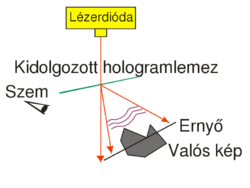
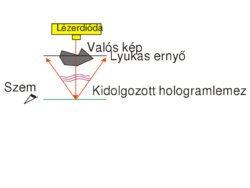
This type of hologram is called transmission hologram, because during reconstruction (Fig. 1/b) the laser source and our eye are at two opposite sides of the hologram, so light has to pass through the hologram in order to each our eye. Besides the virtual image, there is another reconstructed wave (not shown in Fig. 1/b) that is converging and can thus be observed on a screen as the real image of the object. For an off-axis setup the reconstructing waves that create the virtual and the real image, respectively, propagate in two different directions in space. In order to view the real image in a convenient way it is best to use the setup shown in Fig. 1/c. Here a sharp laser beam illuminates a small region of the entire hologram, and the geometry of this sharp reconstructing beam is chosen such that it travels in the opposite direction from what the propagation direction of the reference beam was during recording.
Theoretical background
For the case of amplitude holograms, this is how we can demonstrate that during reconstruction it is indeed the original object wave that is diffracted on the holographic grating. Consider the amplitude of the light wave in the immediate vicinity of the holographic plate. Let the complex amplitude of the two interfering waves during recording be  for the reference wave and
  for the object wave, where R and T are the amplitudes (as real numbers). The amplitude of the reference wave along the plane of the holographic plate, R(x,y), is only slowly changing, so R can be taken to be constant. The intensity distribution along the plate, i.e. the interference pattern that is recorded on the plate can be written as
![\[I_{\rm{exp}}=|\mathbf{r}+\mathbf{t}|^2 = R^2+T^2+\mathbf{rt^*+r^*t}\quad\rm{(1)}\]](/images/math/0/e/5/0e5e499a307e206fcbd6654adb0bd680.png)
 denotes complex conjugate. For an ideal holographic plate with a linear response, the opacity of the final hologram is linearly proportional to this intensity distribution, so the transmittance
  of the plate can be written as
 ![\[\tau=1–\alpha I_{\rm{exp}}\quad\rm{(2)}\]](/images/math/4/3/1/4316070b90b4e57f9bcdaba597113d90.png)
 is the product of a material constant and the time of exposure. When the holographic plate is illuminated with the original reference wave during reconstruction, the complex amplitude just behind the plate is
 ![\[\mathbf{a} = \mathbf{r}\tau=\mathbf{r}(1–\alpha R^2–\alpha T^2)–\alpha\mathbf{r}^2\mathbf{t}^*–\alpha R^2\mathbf{t}\quad\rm{(3)}\]](/images/math/d/3/8/d386e74bb76234220d62f5895d592352.png)
 , is a converging conjugate image (see
  ), and the third term, proportional t, is a copy of the original object wave (note that all proportionality constants are real!) The third term gives a virtual image, because right behind the hologram this term creates a complex wave pattern that is identical to the wave that originally arrived at the same location from the object. Equation (3) is called the fundamental equation of holography. In case of off-axis holograms the three diffraction orders (
 and
and  ) detailed above propagate in three different directions. (Note that if the response of the holographic plate is not linear then higher diffraction orders may also appear.)
Recording and reconstructing a reflection hologram
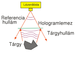
Display holograms that can be viewed in white light are different from the off-axis transmission type discussed above in two respects: (1) they are recorded in an in-line setup, i.e. both the object wave and the reference wave are incident on the holographic plate almost perpendicularly; and (2) they are reflection holograms: during recording the two waves are incident on the plate from two opposite directions, and during reconstruction illumination comes from the same side of the plate as the viewer's eye is. Fig. 2/a shows the recording setup for a reflection hologram. Figs. 2/b and 2/c show the reconstruction setup for the virtual and the real images, respectively.
The reason such holograms can be viewed in white light illumination is that they are recorded on a holographic plate on which the light sensitive layer has a thickness of at least  , much thicker than the wavelength of light. Thick diffraction gratings exhibit the so-called Bragg effect: they have a high diffraction efficiency only at or near the wavelength that was used during recording. Thus if they are illuminated with white light, they selectively diffract only in the color that was used during recording and absorb light at all other wavelengths. Bragg-gratings are sensitive to direction too: the reference wave must have the same direction during reconstruction as it had during recording. Sensitivity to direction also means that the same thick holographic plate can be used to record several distinct holograms, each with a reference wave coming from a different direction. Each hologram is then reconstructed with its own reference wave. (The thicker the material, the more selective it is in direction. A "volume hologram" can store a large number of independent images, e.g. a lot of independent sheets of binary data. This is one of the basic principles behind holographic memories.)
Holographic interferometry
Since the complex amplitude of the reconstructed object wave is determined by the original object itself, e.g. through its shape or surface quality, the hologram stores a certain amount of information about those too. If two states of the same object are recorded on the same holographic plate with the same reference wave, the resulting plate is called a "double-exposure hologram":
![\[I_{12}=|\mathbf r+\mathbf t_1|^2+|\mathbf r+\mathbf t_2|^2=R^2+T^2+\mathbf r\mathbf t_1^*+\mathbf r^*\mathbf t_1+R^2+T^2+\mathbf r\mathbf t_2^*+\mathbf r^*\mathbf t_2=2R^2+2T^2+(\mathbf r\mathbf t_1^*+\mathbf r\mathbf t_2^*)+(\mathbf r^*\mathbf t_1+\mathbf r^*\mathbf t_2)\]](/images/math/0/0/7/0078c0b66dacd94102d005e54b295c25.png)
(Here we assumed that the object wave only changed in phase between the two exposures, but its real amplitude T remained essentially the same. The lower indices denote the two states.) During reconstruction we see the two states "simultaneously":
![\[\mathbf a_{12}=\mathbf r\tau=\mathbf r(1-\alpha I_{12})=\mathbf r(1-2\alpha R^2-2\alpha T^2)-\alpha \mathbf r^2(\mathbf t_1^*+\mathbf t_2^*)+\alpha R^2(\mathbf t_1+\mathbf t_2)\]](/images/math/8/7/d/87ddc9647964e179953751d45f3d011d.png)
i.e. the wave field  contains both a term proportional to
  -el and a term proportional to
  in both the first and the minus first diffraction orders. If we view the virtual image, we only see the contribution of the last terms
  , since all the other diffraction orders propagate in different directions than this. The observed intensity in this diffraction order, apart from the proportionality factor
  , is:
, is:
![\[I_{12,\text{virt}}=|\mathbf a_{12,\text{virt}}|^2=|\mathbf t_1+\mathbf t_2|^2=2T^2+(\mathbf t_1^* \mathbf t_2+\mathbf t_1 \mathbf t_2^*)=2T^2+(\mathbf t_1^* \mathbf t_2+c.c.)\]](/images/math/9/4/f/94f5caf469c66f3743dd11c3b159cc5f.png)
 and
and  ,
, ![\[\mathbf t_1^*\mathbf t_2=T^2e^{i[\varphi_2(x,y)-\varphi_1(x,y)]},\]](/images/math/1/d/a/1da9f8fae36674a1795aeb6b666ca89a.png)
![\[2T^2\cos[\varphi_2(x,y)-\varphi_1(x,y)]\]](/images/math/c/5/2/c524dd642789e50faaf392bad825e5de.png)
 and
and  that determine the interference fringes, you can show that their difference can be written as
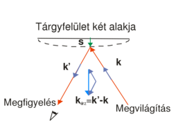
 ![\[\Delta\varphi=\varphi_2-\varphi_1=\vec s\cdot(\vec k'-\vec k)=\vec s\cdot\vec k_\text{sens}\quad\rm{(9)}\]](/images/math/1/2/1/121fb8e08c10a6fd6cde08dae0a1cc16.png)
 is the wave vector of the plane wave that illuminates the object,
  is the wave vector of the beam that travels from the object toward the observer (
 ),
),  is the displacement vector, and
  is the so-called "sensitivity vector". The red arrows in the figure represent arbitrary rays from the expanded beam. Since in a general case the displacement vector is different on different parts of the surface, the phase difference will be space-variant too. We can see from the scalar product that it is only the component of
  that lies along the direction of the sensitivity vector that "can be measured". Both the direction and the length of the sensitivity vector can be changed by controlling the direction of the illumination or the direction of the observation (viewing). This also means that e.g. if we move our viewpoint in front of a double-exposure hologram, the phase difference, and thus the interference fringes, will change too.
We can observe the same kind of fringe pattern if we first make a single exposure hologram of the object, next we place the developed holographic plate back to its original position within a precision of a few tenths of a micron (!), and finally we deform the object while still illuminating it with the same laser beam that we used during recording. In this case the holographically recorded image of the original state interferes with the "live" image of the deformed state. In this kind of interferometry, called the "real-time holographic interferometry", we can change the deformation and observe the corresponding change in the fringe pattern in real time.
Holographic optical elements
If both the object wave and the reference wave are plane waves and they subtend a certain angle, the interference fringe pattern recorded on the hologram will be a simple grating that consists of straight equidistant lines. This is the simplest example of "holographic optical elements" (HOEs). Holography is a simple technique to create high efficiency dispersive elements for spectroscopic applications. The grating constant is determined by the wavelength and angles of incidence of the two plane waves, and can thus be controlled with high precision. Diffraction gratings for more complex tasks (e.g. gratings with space-variant spacing, or focusing gratings) are also easily made using holography: all we have to do is to replace one of the plane waves with a beam having an appropriately designed wavefront.
Since the reconstructed image of a hologram shows the object "as if it were really there", by choosing the object to be an optical device such as a lens or a mirror, we can expect the hologram to work, with some limitations, like the optical device whose image it recorded (i.e. the hologram will focus or reflect light in the same way as the original object did). Such simple holographic lenses and mirrors are further examples of HOEs.
As an example, let's see how, by recording the interference pattern of two simple spherical waves, we can create a "holographic lens". Let's suppose that both spherical waves originate from a point that lies on the optical axis which is perpendicular to the plane of the hologram. (This is a so-called on-axes arrangement.) The distance between the hologram and one spherical wave source (let's call it the reference wave) is , and the distance of the hologram from the other spherical wave source (let's call it the object wave) is
  . Using the well-known parabolic/paraxial approximation of spherical waves, and assuming both spherical waves to have unit amplitudes, the complex amplitudes
  and.
and.  of the reference wave and the object wave, respectively, in a point (x,y) on the holographic plate can be written as
 ![\[\mathbf r=e^{i\frac{2\pi}{\lambda}\left(\frac{x^2+y^2}{2f_1}\right)},\,\mathbf t=e^{i\frac{2\pi}{\lambda}\left(\frac{x^2+y^2}{2f_2}\right)}\quad\rm{(10)}\]](/images/math/1/7/0/1706a6214a80fea2bb97548d644aa4c3.png)
The interference pattern recorded on the hologram becomes:
![\[I=2+e^{i\frac{2\pi}{\lambda}\left(\frac{x^2+y^2}2\left( \frac 1{f_2}-\frac 1{f_1}\right)\right)}+e^{-i\frac{2\pi}{\lambda}\left(\frac{x^2+y^2}2\left( \frac 1{f_2}-\frac 1{f_1}\right)\right)}\quad\rm{(11)}\]](/images/math/3/b/8/3b841288512c58c73b684f4ad7b370b6.png)
and the transmittance  of the hologram can be written again using equation (2), i.e. it will be a linear function of
  . Now, instead of using the reference wave
  , let's reconstruct the hologram with a "perpendicularly incident plane wave" (i.e. with a wave whose complex amplitude in the plane of the hologram is a real constant
  ). This will replace the term
  with the term
  in equation (3), i.e. the complex amplitude of the reconstructed wave just behind the illuminated hologram will be given by the transmittance function
  itself (ignoring a constant factor). This, together with equations (2) and (11) show that the three reconstructed diffraction orders will be:
- a perpendicular plane wave with constant complex amplitude (zero-order),
- a wave with a phase
 (+1st order),
- a wave with a phase
 (-1st order).
We can see from the mathematical form of the phases of the  -orders (reminder: formulas (10)) that these two orders are actually (paraxial) spherical waves that are focused at a distance of
  and
and  from the plane of the hologram, respectively. One of
  and
and  is of course positive and the other is negative, so one diffraction order is a converging spherical wave and the other a diverging spherical wave, both with a focal distance of
  . In summary: by holographically recording the interference of two on-axis spherical waves, we created a HOE that can act both as a "concave" and as a "convex" lens, depending on which diffraction order we use in a given application.
The most important application of HOEs is when we want to replace a complicated optical setup that performs a complex task (e.g. multifocal lenses used for demultiplexing in optical telecommunications) with a single compact hologram. In such cases holography can lead to a significant reduction in size and cost.
Digital holography
Almost immediately after conventional laser holography was developed in the 1960's, scientists became fascinated by the possibility to treat the interference pattern between the reference wave and the object wave as an electronic or digital signal. This either means that we take interference field created by two actually existing wavefronts and store it digitally, or that we calculate the holographic grating pattern digitally and then reconstruct it optically.
The major obstacles that had hindered the development of digital holography for a long time were the following:
- In order to record the fine structure of the object wave and the reference wave, one needs an image input device with a high spatial resolution (at least 100 lines/mm), a high signal-to-noise ratio, and high stability.
- To treat the huge amount of data stored on a hologram requires a large computational power.
- In order to reconstruct the wavefronts optically, one needs a high resolution display.
The subfield of digital holography that deals with digitally computed interference fringes which are then reconstructed optically, is nowadays called "computer holography". The other subfield of digital holography - the one that involves the digital storage of the interference field between physically existing wavefronts - underwent significant progress in the past few years, thanks in part to the spectacular advances in computational power, and in part to the appearance of high resolution CCD and CMOS cameras. On the other hand, spatial light modulators (SLM's) enable us to display a digitally stored holographic fringe pattern in real time. Digital holography has reached a level where we can begin to use it in optical metrology.
Note that there is no fundamental difference between conventional optical holography and digital holography: both share the basic principle of coding phase information as intensity information.
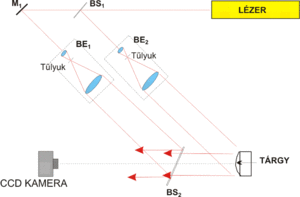
To record a digital hologram, one basically needs to construct the same setup, shown in Fig. 4, that was used in conventional holography. The setup is a Mach-Zehnder interferometer in which the reference wave is formed by passing part of the laser beam through beamsplitter BS1, and beam expander and collimator BE1. The part of the laser beam that is reflected in BS1 passes through beam expander and collimator BE2, and illuminates the object. The light that is scattered from the object (object wave) is brought together with the reference wave at beamsplitter BS2, and the two waves reach the CCD camera together.
The most important difference between conventional and digital holography is the difference in resolution between digital cameras and holographic plates. While the grain size (the "pixel size") of a holographic plate is comparable with the wavelength of visible light, the pixel size of digital cameras is typically one order of magnitude larger, i.e. 4-10 µm. The sampling theorem is only satisfied if the grating constant of the holographic grating is larger than the size of two camera pixels. This means that both the viewing angle of the object as viewed from a point on the camera and the angle between the object wave and reference wave propagation directions must be smaller than a critical limit. In conventional holography, as Fig. 1/a shows, the object wave and the reference wave can make a large angle, digital holography - due to its much smaller spatial resolution - only works in a quasi in-line geometry. A digital camera differs from a holographic plate also in its sensitivity and its dynamic range (signal levels, number of grey levels), so the circumstances of exposure will also be different in digital holography from what we saw in conventional holography above.
As is well-known, the minimum spacing of an interference fringe pattern created by two interfering plane waves is  , where
  is the angle between the two propagation directions. Using this equation and the sampling theorem, we can specify the maximum angle that the object wave and the reference wave can make:
  , where
  is the pixel size of the camera. For visible light and today's digital cameras this angle is typically around
  , hence the in-line geometry shown in Fig. 4.
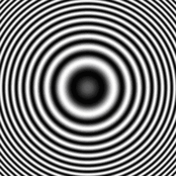
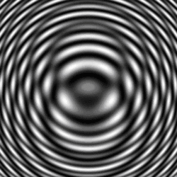
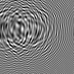
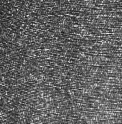
Figure 5 illustrates the appearance of digital holograms. Figs 5/a-c show computer simulated holograms, and Fig. 5/d shows the digital hologram of a real object, recorded in the setup of Fig. 4.
For the numerical reconstruction of digital holograms ("digital reconstruction") we simulate the optical reconstruction of analog amplitude holograms on the computer. If we illuminate a holographic plate (a transparency that introduces amplitude modulation) with a perpendicularly incident plane reference wave, in "digital holography language" this means that the digital hologram can directly be regarded as the amplitude of the wavefront, while the phase of the wavefront is constant. If the reference wave was a spherical wave, the digital hologram has to have the corresponding (space-variant) spherical wave phase, so the wave amplitude at a given pixel will be a complex number.
Thus we have determined the wavefront immediately behind the virtual holographic plate. The next step is to simulate the "propagation" of the wave. Since the physically existing object was at a finite distance from the CCD camera, the propagation has to be calculated for this finite distance too. Since there was no lens in our optical setup, we have to simulate free-space propagation, i.e. we have to calculate a diffraction integral numerically. From the relatively low resolution of the CCD camera and the small propagation angles of the waves we can immediately see that we can apply the parabolic/paraxial Fresnel approximation. This is a great advantage, because the calculation can be reduced to a Fourier transform. In our case the Fresnel approximation of diffraction can be written as
![\[A(u,v)=\frac{i}{\lambda D}e^{\frac{-i\pi}{\lambda D}(u^2+v^2)}\int_{\infty}^{\infty}\int_{\infty}^{\infty}R(x,y)h(x,y) e^{\frac{-i\pi}{\lambda D}(x^2+y^2)}e^{i2\pi(xu+yv)}\textup{d}x\textup{d}y,\]](/images/math/a/f/4/af45dae0275f89c2b7b88949029ea181.png)
 is the complex amplitude distribution of the result (the reconstructed image) - note that this implies a phase information too! -,
  is the digital hologram,
  is the complex amplitude of the reference wave,
  is the distance of reconstruction/object/image from the hologram (from the CCD camera), and
  is the wavelength of light. Using the Fourier transform and switching to discrete numerical coordinates, the expression above can be rewritten as
 ![\[A(u',v')=\frac{i}{\lambda D}e^{\frac{-i\pi}{\lambda D}\left((u'\Delta x')^2+(v'\Delta y')^2\right)}\mathcal F^{-1} \left[R(x,y)h(x,y) e^{\frac{-i\pi}{\lambda D}\left((k\Delta x)^2+(l\Delta y)^2\right)}\right],\]](/images/math/4/b/5/4b50a83f1598f3e0c4d8a9de93e5f26a.png)
We can see that, except for the reconstruction distance D, all the parameters of the numerical reconstruction are given. Distance D, however can - and, in case of an object that has depth, should - be changed relatively freely, around the value of the actual distance between the object and the camera. Hence we can see a sharp image of the object in the intensity distribution formed from the A(u,v). This is similar to adjusting the focus in conventional photography in order to find a distance where all parts of the object look tolerably sharp. We note that the Fourier transform uniquely fixes the pixel size Δx′, Δy′ in the (u,v) image plane according to the formula  where
where  is the (linear) matrix size in the
  direction used in the fast-Fourier-transform-algorithm. This means that the pixel size on the image plane changes proportionally to the reconstruction distance D. This effect must be considered if one wants to interpret the sizes on the image correctly.
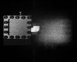
The figure below shows the computer simulated reconstruction of a digital hologram that was recorded in an actual measurement setup. The object was a brass plate (membrane) with a size of 40 mm x 40 mm and a thickness of 0.2mm that was fixed around its perimeter. To improve its reflexivity the object was painted white. The speckled appearance of the object in the Figure is not caused by the painting, but is an unavoidable consequence of a laser illuminating a matte surface. This is a source of image noise in any such measurement. The Figure shows not only the sharp image of the object, but also a very bright spot at the center and a blurred image on the other side of it. These three images are none other than the three diffraction orders that we see in conventional holography too. The central bright spot is the zero-order, the minus first order is the projected real image (that is what we see as the sharp image of the object), and the plus first order corresponds to the virtual image. If the reconstruction is calculated in the opposite direction at a distance -D, what was the sharp image becomes blurred, and vice versa, i.e. the plus and minus first orders are conjugate images, just like in conventional holography.
A digital hologram stores the entire information of the complex wave, and the different diffraction orders are "separated in space" (i.e. they appear at different locations on the reconstructed image), thus the area where the sharp image of the object is seen contains the entire complex amplitude information about the object wave. In principle, it is thus possible to realize the digital version of holographic interferometry. If we record a digital hologram of the original object, then deform the object, and finally record another digital hologram of its deformed state, all we need to perform holographic interferometry is digital data processing.
In double-exposure analog holography it would be the sum, i.e. the interference, of the two waves (each corresponding to a different state of the object) that would generate the contour lines of the displacement field, so that is what we have to simulate now. We numerically calculate the reconstruction of both digital holograms in the appropriate distance and add them. Since the wave fields of the two object states are represented by complex matrices in the calculation, addition is done as a complex operation, point-by-point. The resultant complex amplitude distribution is then converted to an intensity distribution which will display the interference fringes. Alternatively, we can simply consider the phase of the resultant complex amplitude distribution, since we have direct access to it. If, instead of addition, the two waves are subtracted, the bright zero-order spot at the center will disappear.
Speckle pattern interferometry, or TV holography
If a matte diffuser is placed in the reference arm at the same distance from the camera as the object is, the recorded digital hologram is practically impossible to reconstruct, because we don't actually know the phase distribution of the diffuse reference beam in the plane of the camera, i.e. we don't know the complex function R(x,y). If, however, we place an objective in front of the camera and adjust it to create a sharp image of the object, we don't need the reconstruction step any more. What we have recorded in this case is the interference between the object surface and the diffusor as a reference surface. Since each image in itself would have speckles, their interference has speckles too, hence the name "speckle pattern interferometry". Such an image can be observed on a screen in real time (hence the name "TV holography"). A single speckle pattern interferogram in itself does not show anything spectacular. However, if we record two such speckle patterns corresponding to two states of the same object - similarly to double-exposure holography -, these two images can be used to retrieve the information about the change in phase. To do this, all we have to do is to take the absolute value of the difference between the two speckle pattern interferograms.
Measurement tasks
Making a reflection (or display) hologram
In the first part of the lab, we record a white-light hologram of a strongly reflecting, shiny object on a holographic plate with a size of appr.  . The light source is a red laser diode with a nominal power of
  and a wavelength of
  that is connected to a
  battery and takes a current of appr.
  . It is a "bare" laser diode (with no collimating lens placed in front of it), so it emits a diverging beam. The holographic plates are LITIHOLO RRT20 plates: they are glass plates coated with a photosensitive layer that contains photopolymer emulsion and is sensitive to the wavelength range ~500-660 nm. In order to expose the RRT20 plate properly at
  , we need an (average) energy density of at least
  . There is practically no upper limit to this energy density. The emulsion has an intensity threshold below which it gives no response to light at all, so we can use a weak scattered background illumination throughout the measurement. The photosensitive layer has a thickness of
  , much larger than the illuminating wavelength, i.e. it can be used to record volume holograms (see the explanation on Bragg diffraction above). During exposure the intensity variations of the illumination are encoded in the instant film as refractive index modulations in real time. One of the main advantages of this type of holographic plates is that, unlike conventional holographic emulsions, they don't require any chemical process (developing, bleaching, fixing) after exposure. Other photopolymers may require exposure to UV or heat in order to fix the holographic grating in the material, but with the RRT20 plates even such processes are unnecessary: the holographic grating is fixed in its final form automatically during exposure. The holographic plates are kept in a lightproof box which should be opened only immediately before recording and only in a darkened room (with dim background light). Once the holographic plate that will be used for the recording is taken out of the box, the box must be closed again immediately.
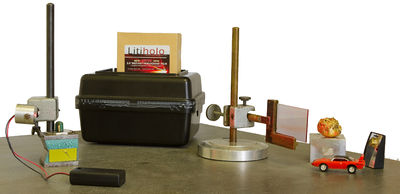
Build the setup of Fig. 2/a inside the wooden box on the optical table. Take a digital photo of the setup you have built. Some of the elements are on magnetic bases. These can be loosened or tightened by turning the knob on them. Use the test plate (and a piece of paper with the same size as the test plate) to trace the size of the beam and to find the appropriate location for the holographic plate for the recording. Place the object on a rectangular block of the appropriate height, so that the expanded beam illuminates the entire object. Put the plate in the special plate holder and fix it in its place with the screws. Make sure that the beam illuminates most of the area of the holographic plate. Put the object as close to the plate as possible. Try to identify the side of the plate which has the light sensitive film on it, and place the plate so that that side of the plate faces the object and the other side faces the laser diode.
Before doing any recording show the setup to the lab supervisor. To record the hologram, first switch off the neon tubes in the room, pull down the blinds on the windows, turn off the laser diode ("output off" on the power supply), then take a holographic plate out of the box and close the box again. Put the plate into the plate holder, wait appr. 30 seconds, then turn on the laser diode again. The minimum exposure time is appr. 5 minutes. You can visually follow the process of the exposure by observing how the brightness of the holographic increases in time, as the interference pattern is developing inside the photosensitive layer. If you are unsure about the proper exposure time, adding another 2 minutes does not hurt. Make sure to eliminate stray lights, movements or vibrations during recording.
When the recording is over, remove the object from its place, and observe the reconstructed virtual image on the hologram, illuminated by the red laser diode. Next, take the hologram out of the plate holder and illuminate it with the high power color and white light LED's you find in the lab. Observe the reconstructed virtual image again. What is the color of the virtual image of the object when the hologram is reconstruced with the white light LED? Does this color change if the angle of illumination or the observation angle change? How does the virtual image look if you flip the hologram? Make a note of your observations and take digital photographs of the reconstructed images.
Note: You can bring your own objects to make a holographic recording of. Among the best objects for this kind of holography are metallic objects (with colors like silver or gold) and white plastic objects.
Investigating a displacement field using real-time holographic interferometry in a reflection hologram setup
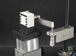
The setup is essentially the same as in the previous measurement, with two differences: the object is now replaced by the deformable membrane, and the illumination must be perpendicular to the membrane surface. We will exploit this perpendicular geometry when applying formula (9). The center of the membrane can be pushed with a micrometer rod. The calibration markings on the micrometer rod correspond to  microns, so one rotation corresponds to a displacement of
  . This rod is rotated through a lever arm fixed to it. The other end of the arm can be rotated with another similar micrometer rod. Measure the arm length of the "outer" rod, i.e. the distance between its touching point and the axis of the "inner" rod, and find the displacement of the center of the membrane that corresponds to one full rotation of the outer rod.
To make a real-time interferogram you first have to record a reflection hologram of the membrane, as described for the previous measurement above. Next, gently rotate the outer micrometer rod through several full rotations (don't touch anything else!) and observe the membrane surface through the hologram. As the membrane is more and more deformed, a fringe pattern with a higher and higher fringe density will appear on the hologram. This fringe pattern is the real-time interferogram and it is caused by the interference between the original state and the deformed state of the membrane. In two or three deformation states make a note of the number of full rotations of the outer rod, and count the corresponding number of fringes that appear on the surface of the membrane with a precision of  fringe. Multiply this by the contour distance of the measurement (see above). Compare the nominal and measured values of the maximum displacement at the center of the membrane. (You can read off the former directly from the micrometer rod, and you can determine the latter from the interferogram). What does the shape of the interference fringes tell you about the displacement field? Once you finish the measurements gently touch the object or the holographic plate. What do you see?
Making a holographic optical element
Repeat the first measurement, using the convex mirror as the object. Observe how the holographic mirror works and make notes on what you observe. How does the mirror image appear in the HOE? How does the HOE work if you flip it and use its other side? What happens if both the illumination and the observation have slanted angles? Is it possible to observe a real, projected image with the HOE? For illumination use the red and white LED's found in the lab or the flashlight of your smartphone. If possible, record your observations on digital photographs.
Making a transmission hologram
Build the transmission hologram setup of Fig. 1/a and make a digital photograph of it. Make sure that the object is properly illuminated and that a sufficiently large portion of it is visible through the "window" that the holographic plate will occupy during recording. Make sure that the angle between the reference beam and the object beam is appr. 30-45 degrees and that their path difference does not exceed 10 cm. Put the holographic plate into the plate holder so that the photosensitive layer faces the two beams. Record the hologram in the same way as described for the first measurement above. Observe the final hologram in laser illumination, using the setups of Fig. 1/b and Fig. 1/c. How can you observe the three-dimensional nature of the reconstructed image in the two reconstruction setups? Could the hologram be reconstructed using a laser with a different wavelength? If possible, make digital photographs of the reconstruction.
Investigating a displacement field using digital holography
In this part of the lab we measure the maximum displacement perpendicular to the plane of a membrane at the center of the membrane. We use the setup shown in Fig. 4, but our actual collimated beams are not perfect plane waves. The light source is a He-Ne gas laser with a power of 35 mW and a wavelength of 632.8 nm. The images are recorded on a Baumer Optronics MX13 monochromatic CCD camera with a resolution of 1280x1024 pixels and a pixel size of 6.7 μm x 6.7 μm. The CCD camera has its own user software. The software displays the live image of the camera (blue film button on the right), and the button under the telescope icon button can be used to manually control the parameters (shutter time, amplification) of the exposure. The optimum value of the amplification is appr. 100-120. The recorded image has a color depth of 8 bits, and its histogram (the number distribution of pixels as a function of grey levels) can be observed using a separate software. When using this software, first click on the "Hisztogram" button, use the mouse to drag the sampling window over the desired part of the image, and double-click to record the histogram. Use the "Timer" button to turn the live tracking of the histogram on and off. Based on the histogram you can decide whether the image is underexposed, overexposed or properly exposed. BS1 is a rotatable beamsplitter with which we can control the intensity ratio between the object arm and the reference arm. In the reference arm there is an additional rotatable beamsplitter which can be used to further attenuate the intensity of the reference wave. The digital holograms are reconstructed with a freeware called HoloVision 2.2 (https://sourceforge.net/projects/holovision/).
Before doing the actual measurement make sure to check the setup and its parameters. Measure the distance of the camera from the object. In the setup the observation direction is perpendicular to the surface of the membrane, but the illumination is not. Determine the illumination angle from distance measurements, and, using equation (9), find the perpendicular displacement of the membrane for which the phase difference is 2π. (Use a rectangular coordinate system that fits the geometry of the membrane.) This will be the so-called contour distance of the measurement.
Check the brightness of the CCD images for the reference beam alone (without the object beam), the object beam alone (without the reference beam), and the interference of the two beams. Adjust the exposure parameters and the rotatable beamsplitters if necessary. The object beam alone and the reference beam alone should not be too dark, but their interference pattern should not be too bright either. Observe the live image on the camera when beamsplitter BS2 is gently touched. How does the histogram of the image look when all the settings are optimal?
Once the exposure parameters are set, record a holographic image, and reconstruct it using HoloVision (Image/Reconstruct command). Include the exposure parameters and the histogram of the digital hologram in your lab report. Check the sharpness of the reconstructed intensity image by looking at the shadow of the frame on the membrane. Observe how the sharpness of the reconstructed image changes if you modify the reconstruction distance by 5 or 10 centimeters in both directions. What reconstruction distance gives the sharpest image? Does this distance differ from the actual measured distance between the object and the CCD camera? If yes, why? What is the pixel size of the image at this distance? How well does the object size on the reconstructed image agree with the actual object size?
Record a digital hologram of the membrane, and then introduce a deformation of less than 5 μm to the membrane. (Use the outer rod described above.) Record another digital hologram. Add the two holograms (Image/Calculations command), and reconstruct the sum. What do you see on the reconstructed intensity image? Include this image in your lab report. Next, reconstruct the difference between the two holograms. How is this reconstructed intensity image different from the previous one? What qualitative information does the fringe system tell you about the displacement field?
Count the number of fringes on the surface of the membrane, from its perimeter to its center, with a precision of  fringe. Multiply this by the contour distance of the measurement, and find the maximum displacement (deformation) Compare this with the nominal value as read from the micrometer rod.
Next, make a speckle pattern interferogram. Attach the photo objective to the camera and place the diffuser into the reference arm in the same distance from the camera as the object is from the camera. By looking, on the image, at the shadow of the frame on the object, adjust the sharpness of the image at an aperture setting of f/2.8 (small aperture). Set the aperture to f/16 (large aperture). If the image is sharp enough, the laser speckles on the object don't move, but only change in brightness, as the object undergoes deformation. Check this. Using the rotatable beam splitters adjust the beam intensities so that the image of the object and the image of the diffuser appear to have the same brightness. Record a speckle pattern in the original state of the object and then another one in the deformed state. Use HoloVision to create the difference of these two speckle patterns, and display its "modulus" (i.e. its absolute value). Interpret what you see on the screen. Try adding the two speckle patterns instead of subtracting them. Why don't you get the same kind of result as in digital holography?
Additional information
For the lab report: you don't need to write a theoretical introduction. Summarize your experiences you had during the lab. Attach photographs of the setups that you actually used. If possible, attach photographs of the reconstructions too. Address all questions that were asked in the lab manual above.
Safety rules: Do not look directly into the laser light, especially into the light of the He-Ne laser used in digital holography. Avoid looking at sharp laser dots on surfaces for long periods of time. Take off shiny objects (jewels, wristwatches). Do not bend down so that your eye level is at the height of the laser beam.'
Links:
