Investigation of High Temperature Superconductors
Superconductivity in a nutshell
Dutch physicist Heike Kamerlingh Onnes was the first to conduct experiments near absolute zero temperature, after building his helium liquefying installation. Within a short amount of time, by 1911, his low temperature measurements have led to a surprising discovery: he found that the resistance of a mercury wire below 4.19 K goes down to zero. Later, it was found that various other materials (eg. lead, tin, aluminium) behave as perfect conductors below a particular temperature. Merely two years later, in 1913, Kamerlingh Onnes was rewarded the Nobel prize for his work.
Following the discovery of superconductivity, nearly half a century needed to pass for a theoretical explanation to be formulated (J. Bardeen, L. Cooper, R. Schiffer – 1957, Nobel prize: 1972). According to the theory, the charges responsible for transporting supercurrent are electron pairs that have special properties, and move through a crystal in a manner different from single electrons. These so called Cooper pairs have been investigated experimentally (Nobel prize: 1973), which later led to the appearance of applications, such as the very high sensitivity magnetometer SQUID devices, the construction of the world's fastest "conventional" computers, or perspectives on superconducting nanostructure based quantum computers.
Since Onnes' discovery, superconductivity has continually been one of the highlighted topics of modern physics. This is shown by the fact that superconductivity-related work has resulted in Nobel prizes in 1987 and 2003 in addition to the above mentioned examples. In 1987 the prize was granted for groundbreaking work on high temperature superconductors, a work of great technical importance as it allows applications based on superconductivity at temperatures closer to liquid nitrogen's boiling temperature, a substance much cheaper and more abundant than helium. Given the appearance of such high temperature superconductors, promising potential in such applications as superconducting motors or long distance transmission lines was also a possibility. The phase transition of such superconducting materials is the focus of study in this laboratory practice.
Another phenomenon related to superconductivity is the so called Meissner effect, discovered in 1933 by Meissner and Ochsenfeld. They demonstrated that below a critical field strength value a magnetic field cannot penetrate the interior of a superconductor, and materials that are cooled down to superconductivity in the presence of finite external fields will expel magnetic fields from within them. The first property may be explained by the creation of a compensating magnetic field, arising from the induction of a persistent electric current (due to the external field changing in time), which does not decay in time within the superconductor due to its zero resistance. The second property, however, goes beyond the bounds of classical electromagnetism.
The zero electrical resistance of the superconducting state enables the creation of very high persistent currents, on the scale of 100 Amperes, by running a current through a superconducting coil, disconnecting the power supply and shorting the two ends of the coil. This current that doesn't decay with time can maintain a magnetic field of several Tesla without further power consumption. This principle is used today by magnetic levitation trains, and medical MRI machines, or the magnets of CERN's particle accelerators. In this lab practice, the persistent current will be studied in a simplified setup. Inside a superconducting ring, the magnetic flux cannot change, as that would have to result in an induced potential; this is not possible due to the zero resistance of the superconductor, which denies any voltage drop. According to this, for a superconducting ring cooled down in a magnetic field, even after the external field is stopped, the magnetic flux inside the ring will remain unchanged, sustained by the persistent current induced inside the ring.
Magnetic field measurement using GMR sensor
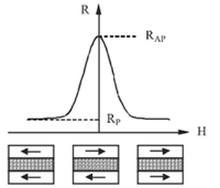
The value of the persistent magnetic field, or the expulsion of the field from inside a superconducting ring can be measured with the same kind of sensor used in hard disk drive head. Such devices, employing the so-called giant magnetoresistance (GMR) effect were discovered in 1988 by Albert Fert and Peter Grünberg, and received the Nobel prize in 2007. The devices are nanostructures made of two ferromagnetic layers, separated by a very thin nonmagnetic layer (see in fig. 1 below). With the right materials and geometry, the magnetization of the two ferromagnetic layers can be designed to be antiparallel in the absence of an external field. Applying a magnetic field to this device can coerce one of the layers to change direction, with the two layers becoming parallel. Due to the GMR effect (fig. 1), the resistance of the device is significantly higher in the antiparallel configuration than the parallel configuration. This means that the applied external magnetic field can be measured as a resistance drop of the device.
| Fig. 1. Simplified depiction of GMR working principle. |
At the basis of this phenomenon lies the fact that electronic transport properties vary based on the direction the electron spin (or magnetic moment) points in, relative to the ferromagnetic layer's magnetization direction. The concept is somewhat similar to that of optical polarization filters: when two polarizing filters are perpendicularly aligned, little light goes through, while when they are parallel, much more light can pass through. It's important to note, however, that GMR only appears in nano-scale devices. If the two ferromagnetic layers are separated by a too thick nonmagnetic layer, then due to various interaction mechanisms, the individual transport electrons "forget" their spin information, and resistance will no longer depend on the orientation of magnetization in the two layers. This is somewhat analogous to inserting an optically diffusive medium between two polarizing filters, which randomly rotates the polarization of light passing through, making the alignment of the two filters irrelevant.
In the electronic industry, the most important application of GMR to this day is with hard disk drive read heads. In the early 90s, these devices used inductive heads for reading. The induced voltage in a small conductive coil in the head was used to read the magnetic information in the rapidly spinning magnetic platters; this imposed a limiting factor on platter capacity. By the second half of the 90s, read heads transitioned to AMR (anisotropic magnetoresistance) based mechanisms, enabling a significant boost in hard drive capacity. However, the AMR effect generates <1% change in resistance, which meant another limiting factor in reading the signal. GMR leads to at least an order of magnitude greater change in resistance (hence its name), allowing a further boost in hard drive capacity by being able to measure signal differences in even smaller geometries.
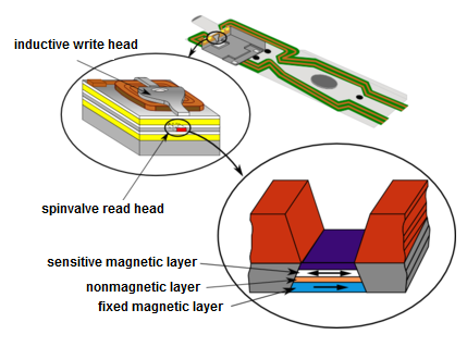
GMR-based read heads use a so called "spin-valve" setup. One of the magnetic layers is "fixed", its magnetization is much harder to change, while the other layer is sensitive to external fields and can freely change its magnetization (see Fig. 2). The sensitive layer will thus change its orientation based on the orientation of magnetically stored bits in the hard drive platter rotating below it. By measuring the resistance of the spinvalve, the bit information is directly accessible.
| Fig. 2. Hard drive head based on GMR working principle. |
Measurement tasks
Safety precautions:
- During the measurements, handle the superconductor materials with care, as they are fragile and somewhat expensive.
- The superconductor materials are toxic if ingested; do not eat during the measurement and make sure to wash your hands thoroughly at the end. Technically, the materials are coated in a protective layer to prevent skin contamination, but precaution is still best practice.
- When working with liquid nitrogen, avoid contact with skin. More importantly, do not touch any objects immersed in liquid nitrogen with your bare hands.
Tools used in this lab
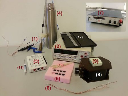
| Fig. 3. Tools and equipment used in this lab. |
Task 1: Measuring phase transition temperature
- Sample holder, consisting of superconducting sample and PT1000 temperature sensor (1)
- Instek Goodwill GDM-8246 digital desktop multimeter (2)
- NI myDaq Data Acquisition Device (3)
- Thermos with liquid nitrogen for cooling (4)
- 100
 and 1k
 resistors
- PC with automated measurement program
Task 2: Persistent current using GMR sensor
- Superconducting ring (5)
- GMR sensor (6)
- Instek Goodwill GDM-8246 digital desktop multimeter (2)
- NI myDaq Data Acquisition Device (3)
- Delta DC Power Supply (7)
- Coil (8)
- Cup for liquid nitrogen (9)
- Tweezers (10)
- PC with automated measurement program
Others:
- Screwdriver (11)
- Wires and banana cables
- Vernier caliper (12)
Task 1: Measuring the phase transition temperature of the superconductor
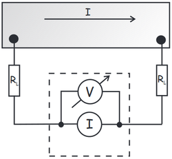
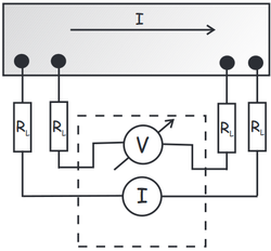
Even in normal conducting state, the samples on the sample holders have a very small resistance, on the order of a few tens of m . Measuring resistance with two terminals in this case will be dominated by the contact resistances as depicted in Fig. 4a. Since the contact resistances are unknown, we will not be able to determine the actual resistance of the sample; and even if we knew the contact resistances, subtracting them from the measured value, the measurement's error will be significant. Instead, we will use four terminal resistance measurement to determine the sample's resistance. This is shown in Fig. 4b. Since no current is running through the sense wires of the voltmeter, there is no voltage drop on the contact resistances. This means that the ratio of voltage measured and current driven into the sample gives the sample's actual resistance with no contact resistance contribution.
| Fig. 4. a) Two terminal resistance measurement. b) Four terminal resistance measurement. | |
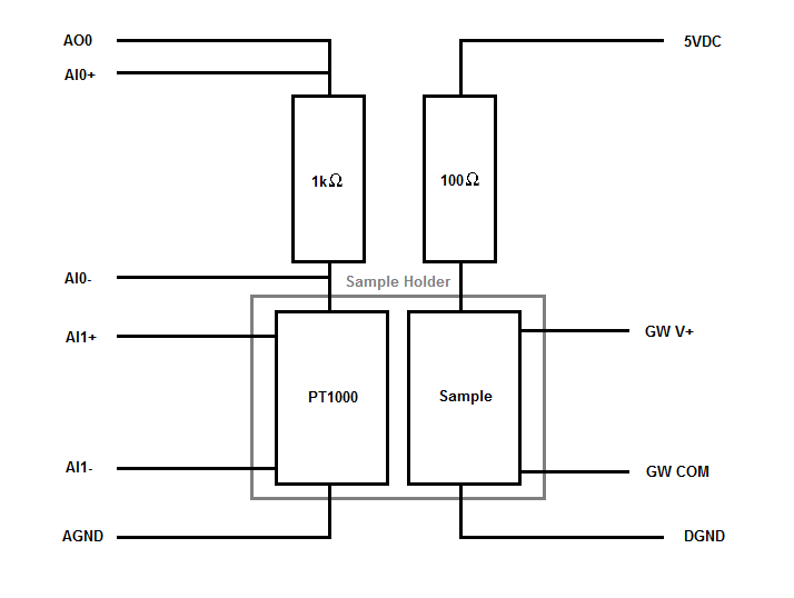
1. Assemble the measurement setup shown in Fig. 5!
| Fig. 5. Connection setup for measuring the phase transition temperature of the superconducting sample, using an NI myDaq and a Goodwill digital multimeter. |
Sample holder pinout:
- The 8 wires of the sample holder (4 for the superconductor, 4 for the PT1000 sensor) are connected via an RS232 socket. The end of the cable is unwound to expose the individual wires, which have to be connected to the rest of the measurement circuit. The wires are arranged by colors, which have to be connected as listed below:
- The superconductor I+/- current bias pair is red/orange and the V+/- sense pair is black/brown.
- The PT 1000 sensor I+/- current bias pair is yellow/purple and the V+/- sense pair is green/blue. The 9th wire (gray) of the RS232 cable is not used.
Measurement principle:
- The superconducting sample has a very low resistance, a few milliohms even at room temperature. The current is therefore defined by the 100 ohm pre-resistor, and the VDC supply. Use this current and the measured voltage on the superconductor to obtain its resistance.
- The PT1000 sensor's resistance changes over the measurement, therefore we use a stable 1k ohm pre-resistor to obtain the current flowing through it, then use that current value and the measured voltage over the PT1000 sensor to obtain its resistance.
Assembly steps:
- Connect the sample holder pins and the two resistors to the myDaq device and Goodwill multimeter pins as shown in Fig. 5. For both the superconducting sample and Pt1000 temperature sensor (in the sample holder), we will use a four terminal measurement setup. The wires are already connected to the elements in the sample holder properly, use the wire colors to identify them.
- Connect the myDaq device to the PC with a USB cable. It will power on automatically.
- Use an RS232-USB converter to connect the Goodwill DMM to the PC. Make sure the Goodwill DMM is off when connecting it to the PC, as the converter is an active circuit which has been known to brick itself if the DMM is already running when it's activated.
- Turn the Goodwill DMM on after it's been properly connected to the PC.
- Set the Goodwill DMM to its most sensitive range by pressing the Shift button and DCV button at the same time.
2. Open and run the measurement program provided. You will use this program to monitor, graph and save the measured temperature sensor and sample resistance output data during the course of the measurement. Note that during subsequent evaluation of the saved data, you will have to consider the nonlinearity of the Pt1000 sensor and the hysteresis error of the sample holder itself; the way to do this is detailed in the supplementary material.
3. Using the measurement program, record the resistance change of the superconducting sample as a function of temperature. The sample holder will be cooled by carefully immersing in the liquid nitrogen thermos. Use a graph measuring Pt1000 resistance over time to estimate cooling rate. You want to take a measurement with as slow a cooling rate as possible. Take note of the sample resistance as a function of temperature, it will suddenly drop to zero near the critical temperature. Once cooled below this temperature, the resistance remains zero. Repeat the measurement while warming up as well: slowly raise the sample holder out of the nitrogen until the temperature starts to rise. You will later use these measurements to precisely determine the critical temperature. Consider the following questions:
- Why does the measured curve differ during the cooling and warming phases of the measurement?
- What kind of measurement errors can occur when trying to measure the temperature?
- What is the uncertainty when measuring sample resistance? What is the largest resistance that the instrument still reads as zero?
Note: To get an estimate of the nonlinearity error of the Pt1000 sensor, you can, after performing the measurement, push the sample holder fully into the liquid. When immersed and after temperature stabilization, the real temperature should be 77K, the temperature of liquid nitrogen. The difference between this and the measured temperature will be the error at 77K. We also know that at 0 Celsius the nonlinearity error is 0.
Task 2: Detecting persistent supercurrent using a GMR sensor
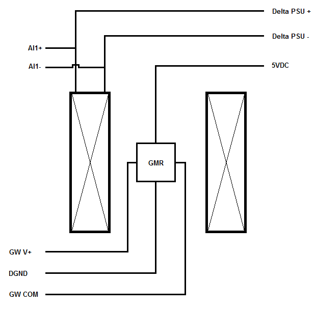
1. Assemble the measurement setup shown in Fig. 6!
| Fig. 6. Connection setup for measuring a persistent current inside a superconductor ring using a GMR sensor. |
Assembly steps:
- First disconnect the previous measurement setup from the myDaq and Goodwill. You can leave the two devices powered and connected to the PC.
- The GMR sensor has four wires: two are the 5V power and ground, the other two are the sensor output. These are color coded in pairs. It doesn't matter which pair you use for power and which for sense.
- Connect the coil inputs to the Delta Power Supply. In parallel, also connect them to the myDaq Analog Input 1 ports so that you can continuously measure the voltage on the coils.
- Make sure the output V/I knobs on the Delta are on zero (rotate CCW until it goes) before you turn it on. Otherwise you could accidentally damage the coil.
- During measurement, always ramp the Delta output to zero before disconnecting from the coil, otherwise it will spark and potentially damage something.
2. Calculate the magnetic field inside the coil as a function of coil voltage. The number of windings and resistance of the coil are written on it, and its length can be determined with the vernier calipers. Use the obtained voltage-field relationship to calibrate the GMR sensor. Use the measurement program to measure and save a calibration curve. Ramp the Delta output from 0 to 0.5 Amperes, optionally in both directions of the coil. Perform this both at room temperature and with the GMR sensor immersed in LN2, as the curve will differ a bit.
3. Now that you can measure magnetic field using your GMR sensor (thanks to the calibration), use the tweezers to place the superconducting ring into the cup. Carefully pour LN2 into the cup as well, so that the ring is fully immersed. Place the GMR sensor inside the ring, and then create a magnetic field of your choosing in the coil (but don't use more than 0.5 Amperes). What does the sensor read? Explain the phenomenon.
4. Stop the magnetic field, remove the GMR sensor and ring from the cup, and pour the LN2 back into the thermos. Wait for the ring to heat up, it should take less than a minute. Place the ring back into the empty cup. Now apply a magnetic field again. With the field on, carefully pour LN2 into the cup again. Then stop the magnetic field. What does the GMR sensor show outside the ring? What does it show when positioned inside the ring? Use the measurement program to monitor the magnetic field inside the superconducting ring on a period of at least 10 minutes. Make sure the LN2 does not run out during measurement. You may then wait for the LN2 to run out and notice what happens with the field measured by the sensor.
- Based on this measurement, give an upper estimate for the resistance of the superconducting ring. The method is detailed in the supplementary material.
- Compared to the uncertainty in the previous task, how much more precise is this measurement?
- Using the uncertainty of the previous task as the upper estimate, what is the amount of time in which the persistent current in the ring should drop to zero?
Supplementary Material
Determination of the critical temperature  is done using both the cooling and warming measurement set. You will notice that there is some offset between the two curves, caused by the transient measurement conditions and the different heat capacities of the sample and the PT1000 sensor. If the experiment were done very slowly, the two curves should coincide due to thermal equilibrium across the sample holder. To measure
  , fit a straight line onto the steep part of the curve, where the resistance drops sharply to zero. Take
  as the point where your straight line meets the x-axis. Using the two obtained values from the two curves as such, you can state that
  is somewhere around the midpoint of these two values, and the error is the difference of the values. That is, the closer the two curves are, the more accurate the
  determination. High measurement accuracy is not part of this exercise's evaluation though, only that this analysis should be performed on the measured data.
To take the nonlinearity of the PT1000 sensor into account, use a second order approximating equation  where
where  is in Celsius and
  is the sensor's resistance at zero Celsius. Solve for
  to get the reverse function
  which you can use in your program to convert the measured resistance to a temperature reading. It is recommended to convert this to Kelvin. As previously mentioned, the remaining error can be corrected for your final
  value by having two known temperatures, the zero Celsius point where the error is zero, and the 77 Kelvin point where you should have a reading by immersing the sample holder fully into LN2 during the exercise. Assume that the error itself increases linearly between these two points, and apply to your obtained
  estimate.
- The PT1000 coefficients according to the ITS-90 standard are
 and
and 
In the second part of the exercise you will use a magnetic coil. The field given by the coil is  , where
  is the voltage applied to the coil,
  is its resistance (written on the side),
  the number of windings which you have to calculate from the length of wire used (written on the side) and the size of the coil, and
  is the height of the coil. During lab measurement it is sufficient to work with
  directly, while for the final submission the
  calculation should be performed and relevant figures should be as a function of
  , not
, not  .
.
In a conducting ring (the superconducting ring) where initial current  is induced, and then voltage supply interrupted, the current over time changes as
  . Here
  is the ring inductance,
  is the inner area of the ring and
  is its height, but
  . The measured magnetic field in the ring is also proportional to this current. From the over-time measurement of magnetic field inside the superconducting ring, you can attempt to estimate
  for which the exponential formula fits the dataset, thus giving an upper limit for the resistance of the ring; compare this value to the measurement precision of the first part of the exercise (note that the point is proving that resistance really is zero, to a much greater precision than in the first part).
Goodwill DMM Programming guide:
using System.IO.Ports;

SerialPort serialPort = new SerialPort("COM##",9600, System.IO.Ports.Parity.None, 8, System.IO.Ports.StopBits.One);

//## <- number of COM port - there are ways to programatically obtain this, but for just 1 static device hard-coding works

serialPort.Handshake = Handshake.None;

serialPort.Open();

//write a message:

serialPort.WriteLine("message");

// if "message" == ":value?", DMM will return front panel reading in Volts

//read (will get stuck if nothing to read on port! handle exception)

string response = serialPort.ReadLine();

//when finished using the connection (end of program):

//serialPort.Flush(); //Flush method csak .Net Micro frameworkben van SerialPorthoz, nem kell, eleg a Close() (de a file streamnel ajanlott)

serialPort.Close();
