Measurements with a Michelson Interferometer
Since a light beam can be modelled as oscillating electric and magnetic field, when two or more beams meet the electric and magnetic fields are added due to the superposition principle. That is in every point of the space the electric and magnetic field is the vectorial sum of fields of each beam.
If the beams originate from different sources, generally there is no connection between the electromagnetic oscillations. In every moment there are points is space where adding the fields results in maximum and points where results in cancellation. Since there is no definite connection, where a maximum was at a given moment, in the next moment there can be a minimum. The frequency of the visible light is too high for the human eye, it will average out the fast oscillation of the intensity.
If the beams originate from the same source, there is a correlation between the phase of the oscillations, so points can exist, where the beams are in phase continously. In this case the total fields are always maximal in these points, and bright spot is visible there. In the points where the beams are always in opposite phase, the total intensity is minimal, a dark spot is visible.
First Thomas Young made interference patterns with two closely placed slits. The resulting image consisted of bright and dark stripes. This experiment was an important proof of the wave nature of light.
The slits can be used as simple interferometer. If the distance between the slits is known, the wavelength of the light can be determined by measuring the distance of the maxima and minima. If the wavelength is known, the distance of the slits can be determined.
Michelson’s interferometer
In 1881, 78 years after Young, A. A. Michelson built a similarily working interferometer.
Michelson’s original intention was to prove the existance of ether – the hypothetical medium which
was considered to be responsible for the propagation of electromagnetic radiation (such as light). Partially his work proves that this hypothesis was wrong. Furthermore, Michelson’s interferometer is widely used to
measure the wavelenght of light, or if it is known, to measure very small displacements.
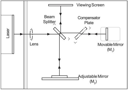
On Fig.1 the sketch of Michelson’s interferometer is shown. The beam of laser is split by a beam splitter, which reflects the 50% of the intensity and transmits the other 50%. One of the split beams is reflected on a fixed, the other is relfected on a movable mirror. Both beams return to the beam splitter. Now the half of light reflected from the movable mirror goes to the screen, also the half of the other beam goes to the screen.
| Fig. 1. Schematics of the Michelson interferometer |
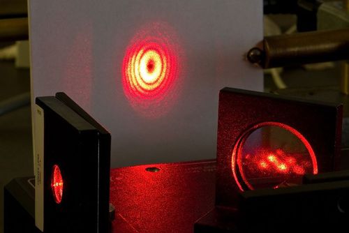
This way the original beam is split to two different paths and a part of them merge again. Since the beams originate from the same source, their phase are strongly correlated. If a lens is used between the laser and the beam splitter, the beams are broadend and an interference pattern consisting of bright and dark rings is visible on the screen (Fig.2).
| Fig. 2. Interference fringes |
Since the two interfering beams of light were split from the same initial beam, they were initially in phase. Their relative phase, when they meet at any point on the screen, depends on the difference in the length of their optical paths before reaching that point.
By moving mirror M1, the path length of one of the beams can be varied. Since the beam traverses the path between M1 and the beam-splitter twice, moving M1 1/4 wavelength nearer the beamsplitter will reduce the optical path of that beam by 1/2 wavelength. The interference pattern will change; the radii of the maxima will be reduced so they now occupy the position of the former minima. If M1 is moved an additional 1/4 wavelength closer to the beam-splitter, the radii of the maxima will again be reduced so maxima and minima trade positions. However, this new arrangement will be indistinguishable from the original pattern.
By slowly moving M1 a measured distance  , and counting
  , the number of times the fringe
pattern is restored to its original state, the wavelength of the light (λ) can be calculated as:
![\[\lambda=\frac{2d_N}{N}\]](/images/math/9/a/3/9a380b222913ff56c9616751148212d0.png)
If the wavelength of the light is known, the same procedure can be used to measure  .
.
From Fig.1 it is evident, that one of the beams crosses the beam splitter only once, while the other three-times. If the light source is strongly coherent and monochromatic, such as a laser, it is not a problem. Although in case of other light sources it can result in error. As the length of optical path increases, the coherence of split beams is decreasing, which can distort the interference pattern.
Using a compensator plate (see Fig.1) both beams crosses glass object three-times, which solves this problem. The compensator plate is similar as the beamsplitter, but without reflecting coating.
With Michelson’s interferometer one can examine optical devices. E.g. placing a lens, as only one of the split beams crosses it, every small deviation of the lens will result in strong distortion of the interference pattern.

